Installation
4.3 Installation and removal procedures
S7-1200 Programmable controller
System Manual, V4.2, 09/2016, A5E02486680-AK
67
Installing and removing a CM or CP
Attach any communication modules to the CPU and install the assembly as a unit, as shown
in Installing and removing the CPU (Page 61).
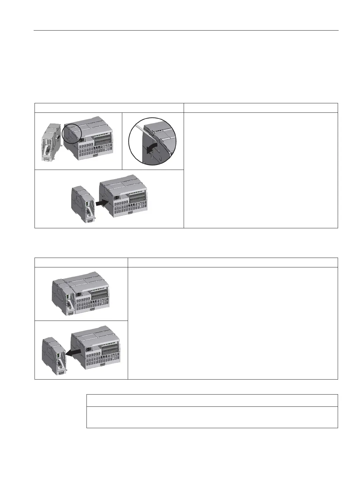
Table 4- 8 Installing a CM or CP
1. Ensure that the CPU and all S7-1200 equipment are
disconnected from electrical power.
2. Attach the CM to the CPU before installing the assembly
as a unit to the DIN rail or panel.
3. Remove the bus cover from the left side of the CPU:
– Insert a screwdriver into the slot above the bus cover.
– Gently pry out the cover at its top.
4. Remove the bus cover. Retain the cover for reuse.
5. Connect the CM or CP to the CPU:
– Align the bus connector and the posts of the CM with
the holes of the CPU
– Firmly press the units together until the posts snap in-
to place.
6. Install the CPU and CP on a DIN rail or panel.
Table 4- 9 Removing a CM or CP
Remove the CPU and CM as a unit from the DIN rail or panel.
1. Ensure that the CPU and all S7-1200 equipment ar
e disconnected from electrical
power.
2. Remove the I/O connectors and all wiring and cables from the CPU and CMs.
3. For DIN rail mounting, move the lower DIN rail clips on the CPU and CMs to the
extended position.
4. Remove the CPU and CMs from the DIN rail or panel.
5. Grasp the CPU and CMs firmly and pull apart.
Separate modules without using a tool.
Do not use a tool to separate the modules because this can damage the units.

 Loading...


