Installation
4.3 Installation and removal procedures
S7-1200 Programmable controller
System Manual, V4.2, 09/2016, A5E02486680-AK
65
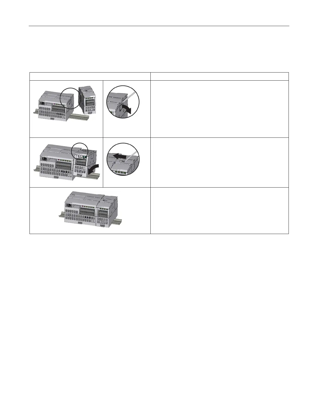
Installing and removing an SM
Table 4- 6 Installing an SM
Install your SM after installing the CPU.
1. Ensure that the CPU and all S7-1200 equipment are discon-
nected from electrical power.
2.
Remove the cover for the connector from the right side of the
CPU:
– Insert a screwdriver into the slot above the cover.
– Gently pry the cover out at its top and remove the cover.
3. Retain the cover for reuse.
Connect the SM to the CPU:
1. Position the SM beside the CPU.
2. Hook the SM over the top of the DIN rail.
3.
Pull out the bottom DIN rail clip to allow the SM to fit over the
rail.
4. Rotate the SM down into position beside the CPU and push
the bottom clip in to latch the SM onto the rail.
Extending the bus connector makes both mechanical and elec-
trical connections for the SM.
1. Place a screwdriver beside the tab on the top of the SM.
2. Slide the tab fully to the left to extend the bus connector into
the CPU.
Follow the same procedure to install a signal module to a signal

 Loading...


