Online and diagnostic tools
15.15 Tracing and recording CPU data on trigger conditions
S7-1200 Programmable controller
System Manual, V4.2, 09/2016, A5E02486680-AK
1347
Tracing and recording CPU data on trigger conditions
STEP 7 provides trace and logic analyzer functions with which you can configure variables
for the PLC to trace and record. You can then upload the recorded trace measurement data
to your programming device and use STEP 7 tools to analyze, manage, and graph your
data. You use the Traces folder in the STEP 7 project tree to create and manage traces.
ace measurement data is available only within the STEP 7 project and is not available
for processing by other tools.
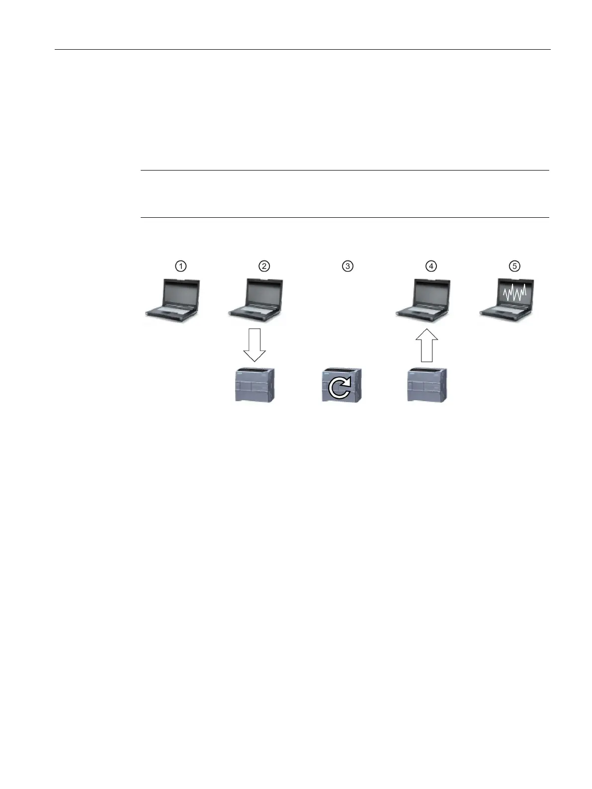
The following figure shows the various steps of the trace feature:
Configure the trace in the trace editor of STEP 7. You can configure the following options:
• Data values to record
• Recording duration
• Recording frequency
• Trigger condition
Transfer the trace configuration from STEP 7 to the PLC.
The PLC executes the program, and when the trigger condition occurs, begins recording the
Transfer the recorded values from the PLC to STEP 7.
Use the tools in STEP 7 to analyze, graphically display, and save the data.
The S7-1200 supports two trace jobs with a maximum of 16 variables captured per trigger
event. Each trace job provides 524288 bytes of RAM for the recording of trace values and
the overhead associated with those values, for example variable addresses and time
stamps.

 Loading...


