Extended instructions
9.7 Diagnostics (PROFINET or PROFIBUS)
S7-1200 Programmable controller
476 System Manual, V4.2, 09/2016, A5E02486680-AK
ModuleStates example configurations
PROFIBUS example
The PROFIBUS example consists of the following:
● 16 PROFIBUS devices named "DPSlave_10" through "DPSlave_25"
● The 16 PROFIBUS devices use PROFIBUS addresses 10 through 25, respectively.
● Each slave device is configured with multiple I/O modules.
● The example uses the LADDR parameter of PROFIBUS slave "DPSlave_12" which
contains a head module, a power module, and two I/O modules.
● The first four bytes of the returned STATE parameter information is displayed.
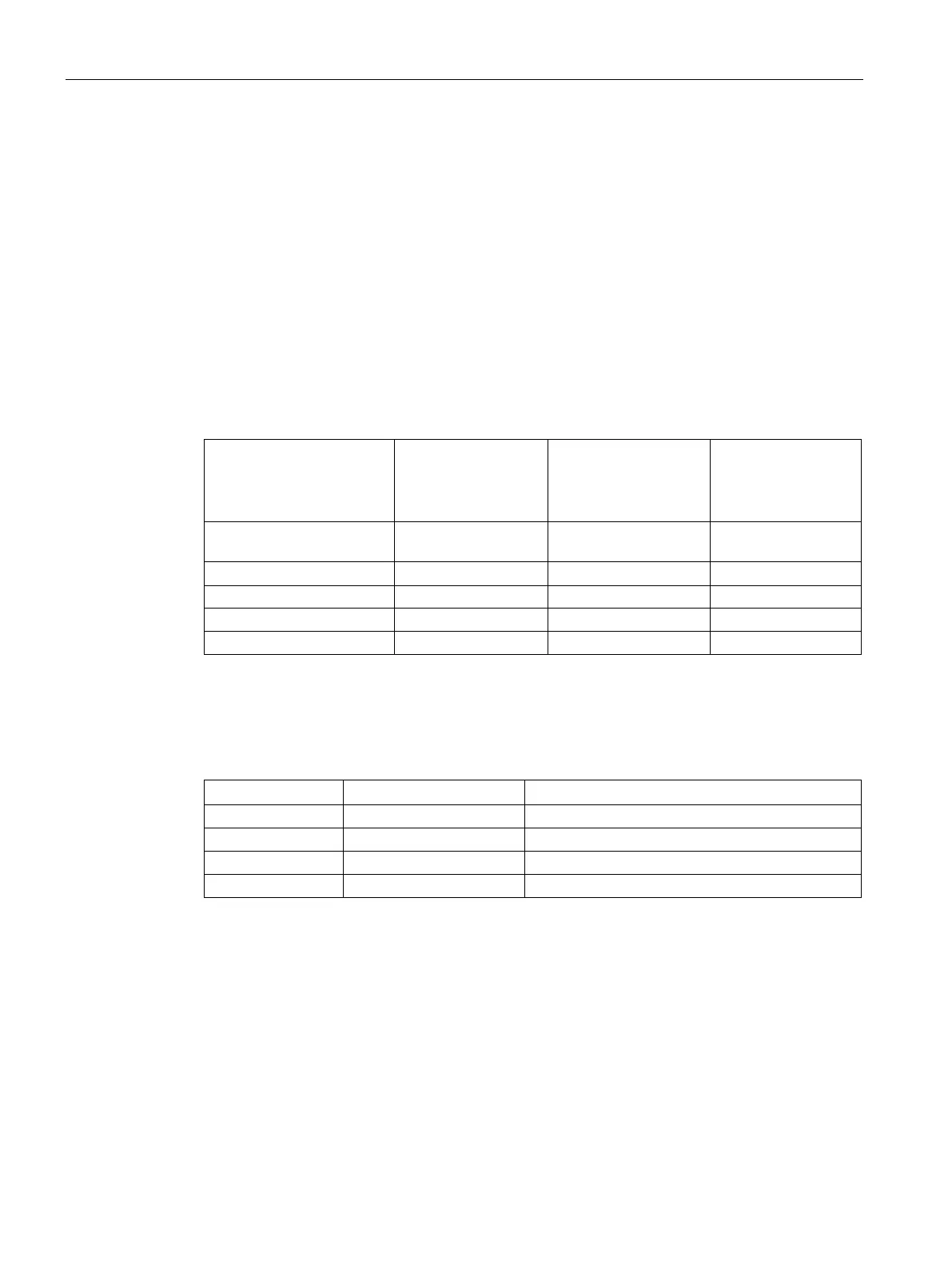
Example 1:
Normal operation with
no errors
Example 2:
PROFIBUS slave de-
vice DPSlave_12 mod-
ule pulled
Example 3:
PROFIBUS slave
device DPSlave_12
disconnected
1: Module configuration
0x1F00_0000 0x1F00_0000 0x1F00_0000
2: Module defective 0x0000_0000 0x0900_0000 0x1F00_0000
4: Module exists 0x1F00_0000 0x1700_0000 0x0000_0000
The following four tables show a binary breakdown of the four bytes of data that are being
analyzed:
Table 9- 170 Example 1: No errors: A value of 0x1F00_0000 is returned for MODE 1 (Module configu-
ration active).
Bit 0 is true; data is available.
Slots 1 (Bit 1) through 4 (Bit 4) contain modules. Slots 5 (Bit 5) an
d beyond do not contain modules.
MODE 4 (Module exists) data matches MODE 1 (Module configuration active), so the configured
modules match the existing modules.

 Loading...


