Installation
4.3 Installation and removal procedures
S7-1200 Programmable controller
70 System Manual, V4.2, 09/2016, A5E02486680-AK
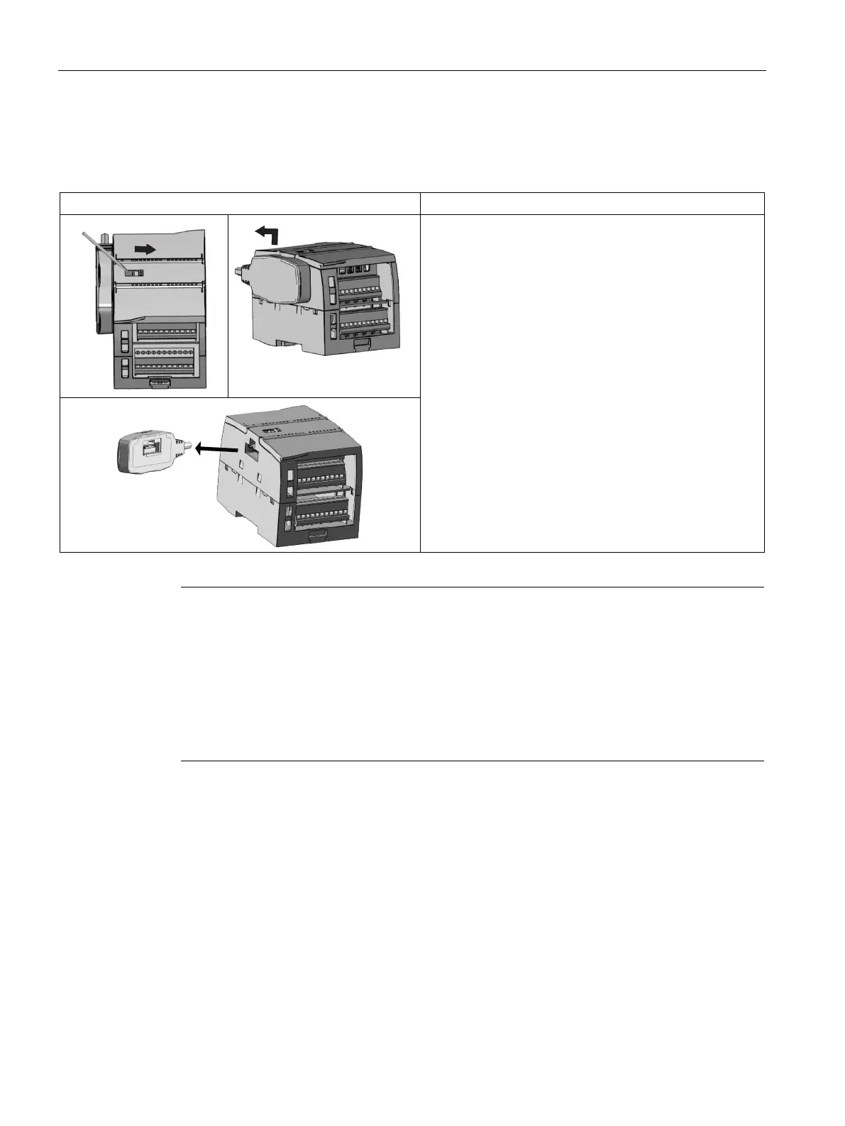
Table 4- 14 Removing the female connector of the expansion cable
1. Ensure that the CPU and all S7-1200 equipment are
disconnected from electrical power.
2. Unlock the connector:
– Place a screwdriver beside the tab on the top of the
signal module.
– Press down slightly and slide the tab fully to the
right.
3. Lift the connector up slightly to disengage the hook
extension.
4. Remove the female connector.
Note
Installing the expansion cable in a vibration environment
If the expansion cable is connected to modules that move
, or are not firmly fixed, the cable
-on connection can gradually become loose.
Use a cable tie to fix the male end cable on the DIN
-rail (or other place) to provide extra
Avoid using excessive force when you pull the cable duri
ng installation. Ensure the cable-
module connection is in the correct position once installation is complete.

 Loading...


