Communication processor and Modbus TCP
13.7 Legacy USS communication (CM/CB 1241 only)
S7-1200 Programmable controller
1242 System Manual, V4.2, 09/2016, A5E02486680-AK
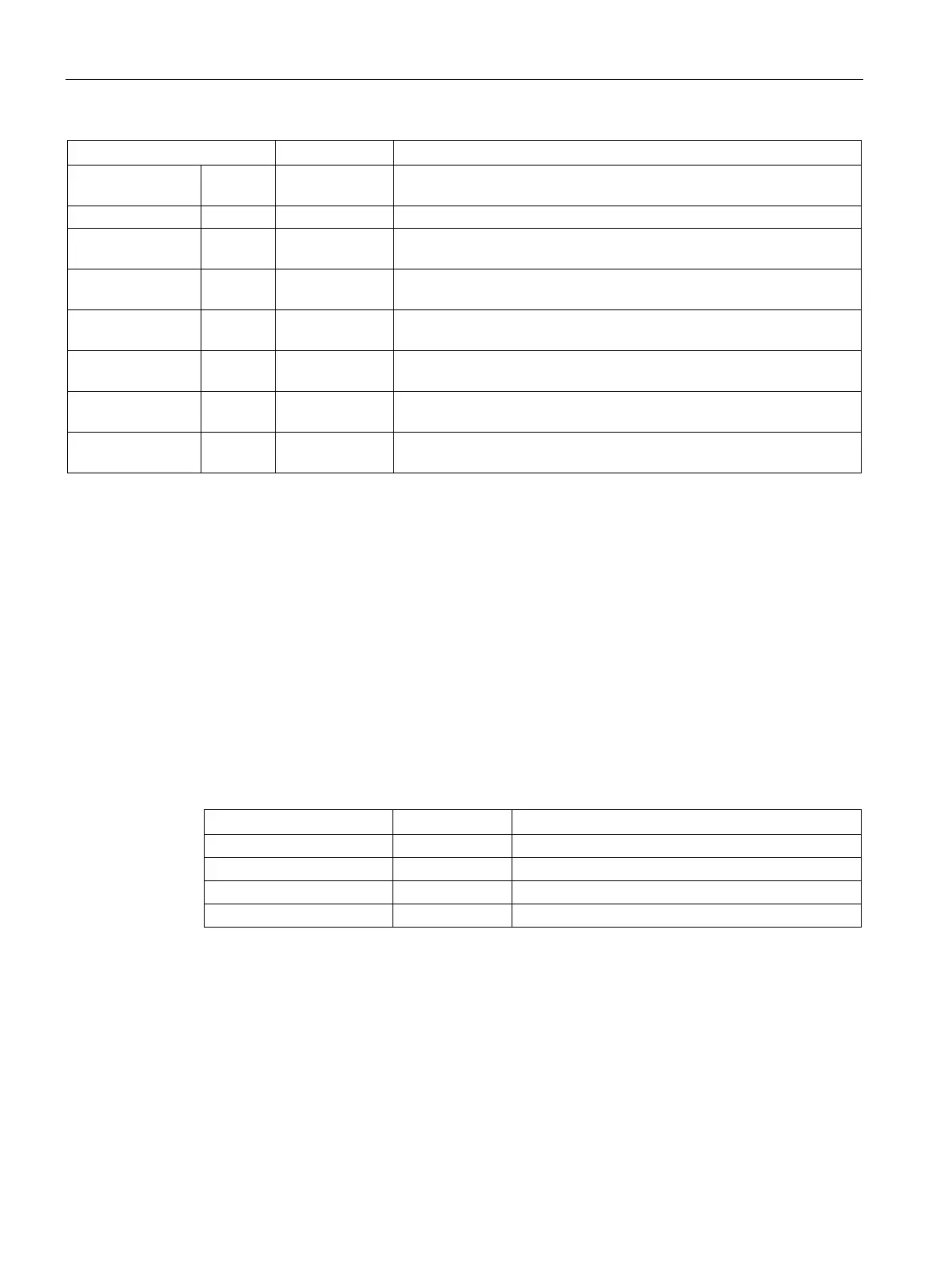
SPEED OUT Real Drive Current Speed (scaled value of drive status word 2): The value of
the speed of the drive as a percentage of configured speed.
STATUS1 OUT Word Drive Status Word 1: This value contains fixed status bits of a drive.
STATUS3 OUT Word Drive Status Word 3: This value contains a user-configurable status
STATUS4 OUT Word Drive Status Word 4: This value contains a user-configurable status
STATUS5 OUT Word Drive Status Word 5: This value contains a user-configurable status
STATUS6 OUT Word Drive Status Word 6: This value contains a user-configurable status
STATUS7 OUT Word Drive Status Word 7: This value contains a user-configurable status
STATUS8 OUT Word Drive Status Word 8: This value contains a user-configurable status
When the initial USS_DRV execution occurs, the drive indicated by the USS address
(parameter DRIVE) is initialized in the Instance DB. After this initialization, subsequent
executions of USS_PORT can begin communication to the drive at this drive number.
Changing the drive number requires a CPU STOP-to-RUN mode transition that initializes the
instance DB. Input parameters are configured into the USS TX message buffer and outputs
are read from a "previous" valid response buffer if any exists. There is no data transmission
during USS_DRV execution. Drives communicate when USS_PORT is executed. USS_DRV
only configures the messages to be sent and interprets data that might have been received
from a previous request.
You can control the drive direction of rotation using either the DIR input (Bool) or using the
sign (positive or negative) with the SPEED_SP input (Real). The following table indicates
how these inputs work together to determine the drive direction, assuming the motor is wired
for forward rotation.
Table 13- 123 Interaction of the SPEED_SP and DIR parameters

 Loading...


