Communication processor and Modbus TCP
13.9 Legacy Modbus RTU communication (CM/CB 1241 only)
S7-1200 Programmable controller
System Manual, V4.2, 09/2016, A5E02486680-AK
1279
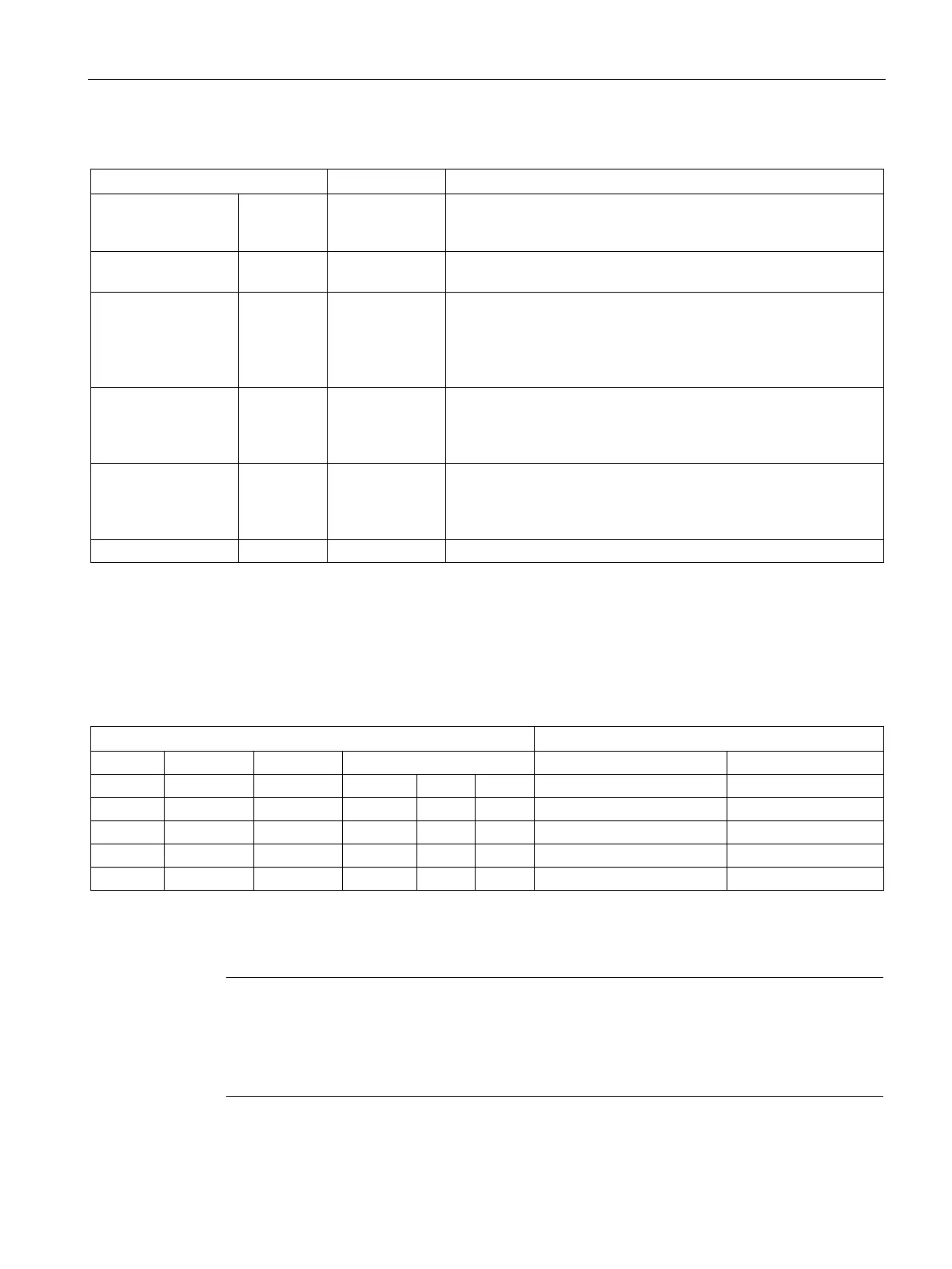
Table 13- 154 Data types for the parameters
MB_ADDR IN V1.0: USInt
V2.0: UInt
The station address of the Modbus slave:
Standard addressing range (1 to 247)
Extended addressing range (0 to 65535)
MB_HOLD_REG IN Variant Pointer to the Modbus Holding Register DB: The Modbus holding
register can be M memory or a data block.
NDR OUT Bool New Data Ready:
• 0 – No new data
• 1 – Indicates that new data has been written by the Modbus
master
DR OUT Bool Data Read:
• 0 – No data read
• 1 – Indicates that data has been read by the Modbus master
ERROR OUT Bool The ERROR bit is TRUE for one scan, after the last request was
terminated with an error. If execution is terminated with an error,
then the error code value at the STATUS parameter is valid only
during the single scan where ERROR = TRUE.
Modbus communication function codes (1, 2, 4, 5, and 15) can read and write bits and words
directly in the input process image and output process image of the CPU. For these function
codes, the MB_HOLD_REG parameter must be defined as a data type larger than a byte.
The following table shows the example mapping of Modbus addresses to the process image
in the CPU.
Table 13- 155 Mapping of Modbus addresses to the process image
Modbus communication function codes (3, 6, 16) use a Modbus holding register which can
be an M memory address range or a data block. The type of holding register is specified by
the MB_HOLD_REG parameter on the MB_SLAVE instruction.
Note
MB_HOLD_REG data block type
A Modbus holding register data block must allow both direct (absolute) and symbolic
addre
ssing. When you create the data block the "Standard" access attribute must be

 Loading...


