Technical specifications
A.7 CPU 1215C
S7-1200 Programmable controller
1416 System Manual, V4.2, 09/2016, A5E02486680-AK
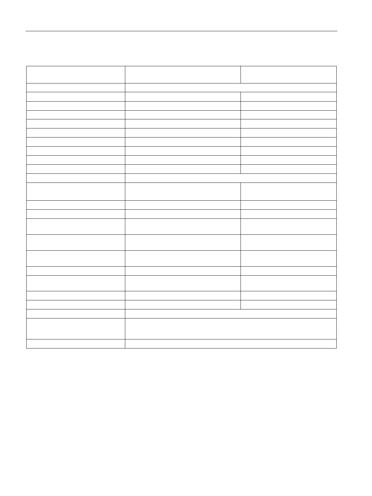
Table A- 74 Digital outputs
CPU 1215C AC/DC/Relay
and CPU 1215C DC/DC/Relay
Type Relay, mechanical Solid state - MOSFET (sourcing)
5 to 30 V DC or 5 to 250 V AC
Logic 1 signal at max. current
Logic 0 signal with 10 KΩ load
Leakage current per point
Isolation (field side to logic) 1500 V AC (coil to contact)
707 V DC (type test)
Isolation (group-to-group)
1
Inductive clamp voltage -- L+ minus 48 V DC,
Switching delay (Qa.0 to Qa.3) 10 ms max. 1.0 μs max., off to on
Switching delay (Qa.4 to Qb.1) 10 ms max. 5 μs max., off to on
Maximum relay switching frequency
Pulse Train Output rate Not recommended
2
100 kHz (Qa.0 to Qa.3)
3
, 2 Hz min.
3
Lifetime mechanical (no load)
10,000,000 open/close cycles
Lifetime contacts at rated load
100,000 open/close cycles
Last value or substitute value (default value 0)
Number of outputs on simultaneously
• 5 (no adjacent points) at 60 °C horizontal or 50 °C vertical
• 10 at 55 °C horizontal or 45 °C vertical
500 m shielded, 150 m unshielded
Relay group-to-group isolation separates line voltage from SELV/PELV and separates different phases up to 250 V AC
line to ground.
For CPU models with relay outputs, you must install a digital signal board (SB) to use the pulse outputs.
Depending on your pulse receiver and cable, an additional load resistor (at least 10% of rated current) may improve
pulse signal quality and noise immunity.

 Loading...


