Technical specifications
A.11 Thermocouple and RTD signal modules (SMs)
S7-1200 Programmable controller
1480 System Manual, V4.2, 09/2016, A5E02486680-AK
Table A- 174 Diagnostics
SM 1231 AI 4 x RTD x 16 bit
SM 1231 AI 8 x RTD x16 bit
1,2
Wire break
3
Yes
1
The overflow, underflow and low voltage diagnostic alarm information will be reported in the analog data values even if
the alarms are disabled in the module configuration.
For resistance ranges underflow detection is never enabled.
When wire break alarm is disabled and an open wire condition exists in the sensor wiring, the module may report ran-
The SM 1231 RTD analog signal module measures the value of resistance connected to the
module inputs. The measurement type can be selected as either "Resistor" or "Thermal
resistor".
● "Resistor": The nominal range full scale value will be decimal 27648.
● "Thermal resistor": The value will be reported in degrees multiplied by ten (for example,
25.3 degrees will be reported as decimal 253). The climatic range values will be reported
in degrees multiplied by one hundred (for example, 25.34 degrees will be reported as
decimal 2534).
The SM 1231 RTD module supports measurements with 2-wire, 3-wire and 4-wire
connections to the sensor resistor.
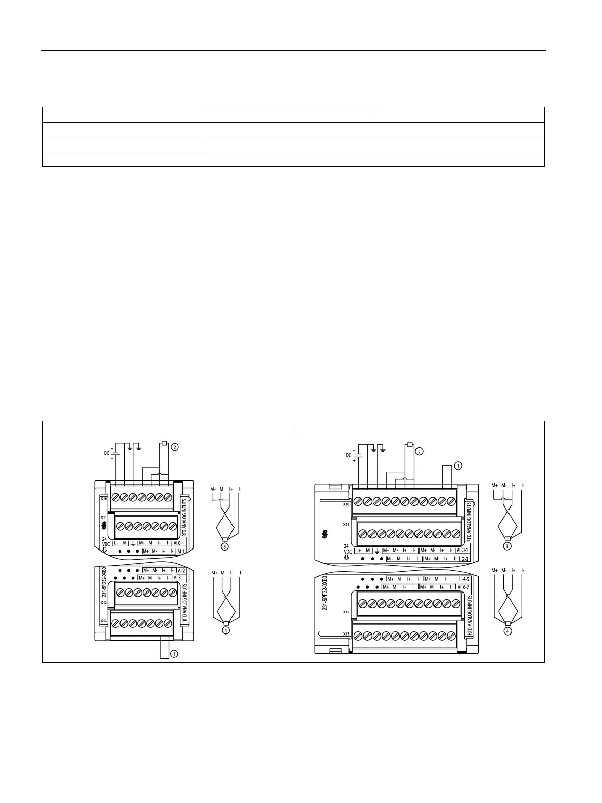
Table A- 175 Wiring diagrams for the RTD SMs
SM 1231 RTD 4 x 16 bit (6ES7231-5PD32-0XB0)
SM 1231 RTD 8 x 16 bit (6ES7231-5PF32-0XB0)
Loop-back unused RTD inputs
2-wire RTD ③ 3-wire RTD ④ 4-wire RTD
NOTE: Connectors must be gold. See Appendix C, Spare Parts for article number.

 Loading...


