Technical specifications
A.17 TeleService (TS Adapter and TS Adapter modular)
S7-1200 Programmable controller
System Manual, V4.2, 09/2016, A5E02486680-AK
1545
Isolation
RS485 signal to chassis ground
RS485 signal to CPU logic common
707 V DC (type test)
Cable length, shielded 1000 m max. (baud rate dependent)
Baud rate 300 baud, 600 baud, 1.2 kbits, 2.4 kbits, 4.8 kbits, 9.6 kbits (default),
19.2 kbits, 38.4 kbits, 57.6 kbits, 76.8 kbits, 115.2 kbits
Parity No parity (default), even, odd, Mark (parity bit always set to 1),
Space (parity bit always set to 0)
XON/XOFF supported for the RS422 mode
Table A- 255 Power supply
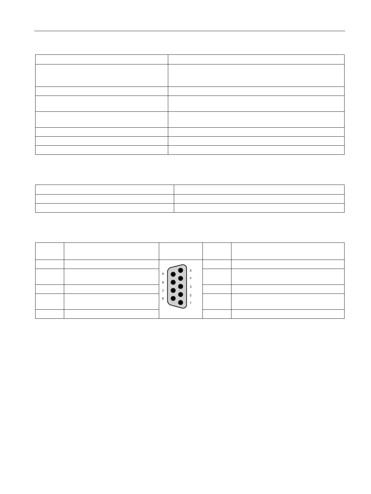
Table A- 256 RS485 or RS422 connector (female)
Logic or communication ground
+5 V with 100 ohm series resistor: Output
2 TxD+
1
Connected for RS422
Not used for RS485: Output
7 Not connected
2
Signal B (RxD/TxD+): Input/Output
2
Signal A (RxD/TxD-): Input/Output
4 RTS
3
Request to send (TTL level) Output 9 TXD-
1
Connected for RS422
Not used for RS485: Output
Logic or communication ground
Pin 2 (TxD+) and Pin 9 (TxD-) are the RS422 transmit signals.
Pin 3 (RxD/Tx+) and Pin 8 (RxD/TxD-) are RS485 transmit and receive signals. For RS422, Pin 3 is RxD+ and Pin 8 is
RxD-.
The RTS is a TTL level signal and can be used to control another half duplex device based on this signal. It is active
when you transmit and is inactive all other times.

 Loading...


