Home
Siemens
Controller
SIMATIC S7-1200
System Manual
Page 575
Siemens SIMATIC S7-1200 - Page 575
1614 pages
Manual
To Next Page
To Next Page
To Previous Page
To Previous Page
Loading...
Technology instr
uctio
ns
10.1
Cou
nting (H
igh
-
speed c
ounters)
S7
-
1200 Programmable
controller
System Manual
,
V4.2, 09/2016
,
A5E02486680
-
AK
575
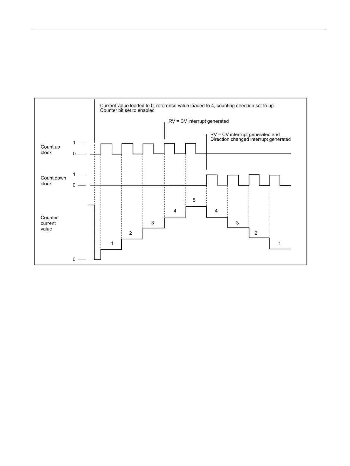
Two phase
Two phas
e counts:
●
Up on the
clock up
input
●
Down on t
he clock
down input
574
576
Table of Contents
Main Page
S7-1200 Programmable controller
1
Preface
3
Table of contents
7
1 Product overview
27
1.1 Introducing the S7-1200 PLC
27
1.2 Expansion capability of the CPU
30
1.3 Basic HMI panels
32
2 New features
33
3 STEP 7 programming software
37
3.1 System requirements
38
3.2 Different views to make the work easier
39
3.3 Easy-to-use tools
41
3.3.1 Inserting instructions into your user program
41
3.3.2 Accessing instructions from the "Favorites" toolbar
41
3.3.3 Creating a complex equation with a simple instruction
42
3.3.4 Adding inputs or outputs to a LAD or FBD instruction
44
3.3.5 Expandable instructions
44
3.3.6 Selecting a version for an instruction
45
3.3.7 Modifying the appearance and configuration of STEP 7
45
3.3.8 Dragging and dropping between editors
46
3.3.9 Changing the operating mode of the CPU
47
3.3.10 Changing the call type for a DB
48
3.3.11 Temporarily disconnecting devices from a network
49
3.3.12 Virtual unplugging of devices from the configuration
50
3.4 Backward compatibility
51
4 Installation
53
4.1 Guidelines for installing S7-1200 devices
53
4.2 Power budget
56
4.3 Installation and removal procedures
57
4.3.1 Mounting dimensions for the S7-1200 devices
57
4.3.2 Installing and removing the CPU
61
4.3.3 Installing and removing an SB, CB, or BB
63
4.3.4 Installing and removing an SM
65
4.3.5 Installing and removing a CM or CP
67
4.3.6 Removing and reinstalling the S7-1200 terminal block connector
68
4.3.7 Installing and removing the expansion cable
69
4.3.8 TS (TeleService) adapter
71
4.3.8.1 Connecting the TeleService adapter
71
4.3.8.2 Installing the SIM card
73
4.3.8.3 Installing the TS adapter unit on a DIN rail
74
4.3.8.4 Installing the TS adapter on a panel
75
4.4 Wiring guidelines
76
5 PLC concepts
83
5.1 Execution of the user program
83
5.1.1 Operating modes of the CPU
87
5.1.2 Processing the scan cycle in RUN mode
91
5.1.3 Organization blocks (OBs)
92
5.1.3.1 Program cycle OB
92
5.1.3.2 Startup OB
93
5.1.3.3 Time delay interrupt OB
93
5.1.3.4 Cyclic interrupt OB
94
5.1.3.5 Hardware interrupt OB
95
5.1.3.6 Time error interrupt OB
96
5.1.3.7 Diagnostic error interrupt OB
97
5.1.3.8 Pull or plug of modules OB
100
5.1.3.9 Rack or station failure OB
101
5.1.3.10 Time of day OB
102
5.1.3.11 Status OB
102
5.1.3.12 Update OB
103
5.1.3.13 Profile OB
103
5.1.3.14 MC-Servo and MC-Interpolator OB
103
5.1.3.15 MC-PreServo
104
5.1.3.16 MC-PostServo
105
5.1.3.17 Event execution priorities and queuing
105
5.1.4 Monitoring and configuring the cycle time
109
5.1.5 CPU memory
110
5.1.5.1 System and clock memory
112
5.1.6 Diagnostics buffer
114
5.1.7 Time of day clock
115
5.1.8 Configuring the outputs on a RUN-to-STOP transition
116
5.2 Data storage, memory areas, I/O and addressing
117
5.2.1 Accessing the data of the S7-1200
117
5.3 Processing of analog values
123
5.4 Data types
125
5.4.1 Bool, Byte, Word, and DWord data types
126
5.4.2 Integer data types
127
5.4.3 Floating-point real data types
127
5.4.4 Time and Date data types
128
5.4.5 Character and String data types
130
5.4.6 Array data type
132
5.4.7 Data structure data type
133
5.4.8 PLC data type
133
5.4.9 Variant pointer data type
134
5.4.10 Accessing a "slice" of a tagged data type
134
5.4.11 Accessing a tag with an AT overlay
135
5.5 Using a memory card
138
5.5.1 Inserting a memory card in the CPU
139
5.5.2 Configuring the startup parameter of the CPU before copying the project to the memory card
142
5.5.3 Transfer card
142
5.5.4 Program card
145
5.5.5 Firmware update
148
5.6 Recovery from a lost password
151
6 Device configuration
153
6.1 Inserting a CPU
154
6.2 Uploading the configuration of a connected CPU
156
6.3 Adding modules to the configuration
158
6.4 Configuration control
159
6.4.1 Advantages and applications of configuration control
159
6.4.2 Configuring the central installation and optional modules
159
6.4.3 Example of configuration control
166
6.5 Changing a device
170
6.6 Configuring the operation of the CPU
170
6.6.1 Overview
170
6.6.2 Configuring digital input filter times
172
6.6.3 Pulse catch
174
6.7 Configuring multilingual support
175
6.8 Configuring the parameters of the modules
177
6.9 Configuring the CPU for communication
179
6.10 Time synchronization
181
7 Programming concepts
183
7.1 Guidelines for designing a PLC system
183
7.2 Structuring your user program
185
7.3 Using blocks to structure your program
187
7.3.1 Organization block (OB)
188
7.3.2 Function (FC)
190
7.3.3 Function block (FB)
190
7.3.4 Data block (DB)
192
7.3.5 Creating reusable code blocks
194
7.3.6 Passing parameters to blocks
195
7.4 Understanding data consistency
198
7.5 Programming language
199
7.5.1 Ladder logic (LAD)
199
7.5.2 Function Block Diagram (FBD)
200
7.5.3 SCL
201
7.5.3.1 SCL program editor
201
7.5.3.2 SCL expressions and operations
202
7.5.3.3 Indexed addressing with PEEK and POKE instructions
206
7.5.4 EN and ENO for LAD, FBD and SCL
208
7.6 Protection
210
7.6.1 Access protection for the CPU
210
7.6.2 External load memory
212
7.6.3 Know-how protection
213
7.6.4 Copy protection
214
7.7 Downloading the elements of your program
216
7.8 Synchronizing the online CPU and offline project
219
7.9 Uploading from the online CPU
221
7.9.1 Comparing the online CPU to the offline CPU
221
7.10 Debugging and testing the program
222
7.10.1 Monitor and modify data in the CPU
222
7.10.2 Watch tables and force tables
223
7.10.3 Cross reference to show usage
223
7.10.4 Call structure to examine the calling hierarchy
225
8 Basic instructions
227
8.1 Bit logic operations
227
8.1.1 Bit logic instructions
227
8.1.2 Set and reset instructions
230
8.1.3 Positive and negative edge instructions
233
8.2 Timer operations
236
8.3 Counter operations
244
8.4 Comparator operations
250
8.4.1 Compare values instructions
250
8.4.2 IN_Range (Value within range) and OUT_Range (Value outside range)
251
8.4.3 OK (Check validity) and NOT_OK (Check invalidity)
252
8.4.4 Variant and array comparison instructions
253
8.4.4.1 Equality and non-equality comparison instructions
253
8.4.4.2 Null comparsion instructions
254
8.4.4.3 IS_ARRAY (Check for ARRAY)
254
8.5 Math functions
255
8.5.1 CALCULATE (Calculate)
255
8.5.2 Add, subtract, multiply and divide instructions
257
8.5.3 MOD (return remainder of division)
258
8.5.4 NEG (Create twos complement)
259
8.5.5 INC (Increment) and DEC (Decrement)
259
8.5.6 ABS (Form absolute value)
260
8.5.7 MIN (Get minimum) and MAX (Get maximum)
261
8.5.8 LIMIT (Set limit value)
262
8.5.9 Exponent, logarithm, and trigonometry instructions
263
8.6 Move operations
265
8.6.1 MOVE (Move value), MOVE_BLK (Move block), UMOVE_BLK (Move block uninterruptible), and MOVE_BLK_VARIANT (Move block)
265
8.6.2 Deserialize
269
8.6.3 Serialize
272
8.6.4 FILL_BLK (Fill block) and UFILL_BLK (Fill block uninterruptible)
275
8.6.5 SWAP (Swap bytes)
276
8.6.6 LOWER_BOUND: (Read out ARRAY low limit)
277
8.6.7 UPPER_BOUND: (Read out ARRAY high limit)
279
8.6.8 Read / Write memory instructions
281
8.6.8.1 PEEK and POKE (SCL only)
281
8.6.8.2 Read and write big and little Endian instructions (SCL)
283
8.6.9 Variant instructions
285
8.6.9.1 VariantGet (Read VARIANT tag value)
285
8.6.9.2 VariantPut (Write VARIANT tag value)
286
8.6.9.3 CountOfElements (Get number of ARRAY elements)
287
8.6.10 Legacy instructions
288
8.6.10.1 FieldRead (Read field) and FieldWrite (Write field) instructions
288
8.7 Conversion operations
290
8.7.1 CONV (Convert value)
290
8.7.2 Conversion instructions for SCL
291
8.7.3 ROUND (Round numerical value) and TRUNC (Truncate numerical value)
294
8.7.4 CEIL and FLOOR (Generate next higher and lower integer from floating-point number)
295
8.7.5 SCALE_X (Scale) and NORM_X (Normalize)
296
8.7.6 Variant conversion instructions
299
8.7.6.1 VARIANT_TO_DB_ANY (Convert VARIANT to DB_ANY)
299
8.7.6.2 DB_ANY_TO_VARIANT (Convert DB_ANY to VARIANT)
300
8.8 Program control operations
302
8.8.1 JMP (Jump if RLO = 1), JMPN (Jump if RLO = 0), and Label (Jump label) instructions
302
8.8.2 JMP_LIST (Define jump list)
303
8.8.3 SWITCH (Jump distributor)
304
8.8.4 RET (Return)
306
8.8.5 ENDIS_PW (Enable/disable CPU passwords)
307
8.8.6 RE_TRIGR (Restart cycle monitoring time)
309
8.8.7 STP (Exit program)
310
8.8.8 GET_ERROR and GET_ERROR_ID (Get error and error ID locally) instructions
311
8.8.9 RUNTIME (Measure program runtime)
314
8.8.10 SCL program control statements
316
8.8.10.1 Overview of SCL program control statements
316
8.8.10.2 IF-THEN statement
317
8.8.10.3 CASE statement
318
8.8.10.4 FOR statement
320
8.8.10.5 WHILE-DO statement
321
8.8.10.6 REPEAT-UNTIL statement
322
8.8.10.7 CONTINUE statement
323
8.8.10.8 EXIT statement
324
8.8.10.9 GOTO statement
325
8.8.10.10 RETURN statement
325
8.9 Word logic operations
326
8.9.1 AND, OR, and XOR logic operation instructions
326
8.9.2 INV (Create ones complement)
327
8.9.3 DECO (Decode) and ENCO (Encode) instructions
327
8.9.4 SEL (Select), MUX (Multiplex), and DEMUX (Demultiplex) instructions
329
8.10 Shift and rotate
332
8.10.1 SHR (Shift right) and SHL (Shift left) instructions
332
8.10.2 ROR (Rotate right) and ROL (Rotate left) instructions
333
9 Extended instructions
335
9.1 Date, time-of-day, and clock functions
335
9.1.1 Date and time-of-day instructions
335
9.1.2 Clock functions
338
9.1.3 TimeTransformationRule data structure
342
9.1.4 SET_TIMEZONE (Set timezone)
343
9.1.5 RTM (Runtime meters)
344
9.2 String and character
346
9.2.1 String data overview
346
9.2.2 S_MOVE (Move character string)
346
9.2.3 String conversion instructions
347
9.2.3.1 S_CONV, STRG_VAL, and VAL_STRG (Convert to/from character string and number) instructions
347
9.2.3.2 Strg_TO_Chars and Chars_TO_Strg (Convert to/from character string and array of CHAR) instructions
357
9.2.3.3 ATH and HTA (Convert to/from ASCII string and hexadecimal number) instructions
359
9.2.4 String operation instructions
361
9.2.4.1 MAX_LEN (Maximum length of a character string)
361
9.2.4.2 LEN (Determine the length of a character string)
362
9.2.4.3 CONCAT (Combine character strings)
363
9.2.4.4 LEFT, RIGHT, and MID (Read substrings in a character string) instructions
364
9.2.4.5 DELETE (Delete characters in a character string)
365
9.2.4.6 INSERT (Insert characters in a character string)
366
9.2.4.7 REPLACE (Replace characters in a character string)
367
9.2.4.8 FIND (Find characters in a character string)
369
9.2.5 Runtime information
370
9.2.5.1 GetSymbolName (Read out a tag on the input parameter)
370
9.2.5.2 GetSymbolPath (Query composite global name of the input parameter assignment)
373
9.2.5.3 GetInstanceName (Read out name of the block instance)
376
9.2.5.4 GetInstancePath (Query composite global name of the block instance)
379
9.2.5.5 GetBlockName (Read out name of the block)
381
9.3 Distributed I/O (PROFINET, PROFIBUS, or AS-i)
384
9.3.1 Distributed I/O Instructions
384
9.3.2 RDREC and WRREC (Read/write data record)
385
9.3.3 GETIO (Read process image)
388
9.3.4 SETIO (Transfer process image)
389
9.3.5 GETIO_PART (Read process image area)
390
9.3.6 SETIO_PART (Transfer process image area)
392
9.3.7 RALRM (Receive interrupt)
394
9.3.8 D_ACT_DP (Enable/disable PROFINET IO devices)
398
9.3.9 STATUS parameter for RDREC, WRREC, and RALRM
403
9.3.10 Others
408
9.3.10.1 DPRD_DAT and DPWR_DAT (Read/write consistent data)
408
9.3.10.2 RCVREC (I-device/I-slave receive data record)
411
9.3.10.3 PRVREC (I-device/I-slave make data record available)
413
9.3.10.4 DPNRM_DG (Read diagnostic data from a PROFIBUS DP slave)
416
9.4 PROFIenergy
419
9.5 Interrupts
420
9.5.1 ATTACH and DETACH (Attach/detach an OB and an interrupt event) instructions
420
9.5.2 Cyclic interrupts
424
9.5.2.1 SET_CINT (Set cyclic interrupt parameters)
424
9.5.2.2 QRY_CINT (Query cyclic interrupt parameters)
426
9.5.3 Time of day interrupts
427
9.5.3.1 SET_TINTL (Set time of day interrupt)
428
9.5.3.2 CAN_TINT (Cancel time of day interrupt)
429
9.5.3.3 ACT_TINT (Activate time of day interrupt)
430
9.5.3.4 QRY_TINT (Query status of time of day interrupt)
431
9.5.4 Time delay interrupts
432
9.5.5 DIS_AIRT and EN_AIRT (Delay/enable execution of higher priority interrupts and asynchronous error events) instructions
435
9.6 Alarms
436
9.6.1 Gen_UsrMsg (Generate user diagnostic alarms)
436
9.7 Diagnostics (PROFINET or PROFIBUS)
439
9.7.1 Diagnostic instructions
439
9.7.2 RD_SINFO (Read current OB start information)
440
9.7.3 LED (Read LED status)
450
9.7.4 Get_IM_Data (Read the identification and maintenance data)
451
9.7.5 Get_Name (Read the name of a PROFINET IO device)
453
9.7.6 GetStationInfo (Read the IP or MAC address of a PROFINET IO device)
460
9.7.7 DeviceStates instruction
468
9.7.7.1 DeviceStates example configurations
469
9.7.8 ModuleStates instruction
474
9.7.8.1 ModuleStates example configurations
476
9.7.9 GET_DIAG (Read diagnostic information)
480
9.7.10 Diagnostic events for distributed I/O
486
9.8 Pulse
487
9.8.1 CTRL_PWM (Pulse width modulation)
487
9.8.2 CTRL_PTO (Pulse train output)
488
9.8.3 Operation of the pulse outputs
492
9.8.4 Configuring a pulse channel for PWM or PTO
494
9.9 Recipes and Data logs
498
9.9.1 Recipes
498
9.9.1.1 Recipe overview
498
9.9.1.2 Recipe example
499
9.9.1.3 Program instructions that transfer recipe data
502
9.9.1.4 Recipe example program
506
9.9.2 Data logs
509
9.9.2.1 Data log record structure
509
9.9.2.2 Program instructions that control data logs
510
9.9.2.3 Working with data logs
525
9.9.2.4 Limit to the size of data log files
526
9.9.2.5 Data log example program
529
9.10 Data block control
534
9.10.1 CREATE_DB (Create data block)
534
9.10.2 READ_DBL and WRIT_DBL (Read/write a data block in load memory) instructions
538
9.10.3 ATTR_DB (Read data block attribute)
541
9.10.4 DELETE_DB (Delete data block)
542
9.11 Address handling
544
9.11.1 GEO2LOG (Determine the hardware identifier from the slot)
544
9.11.2 LOG2GEO (Determine the slot from the hardware identifier)
546
9.11.3 IO2MOD (Determine the hardware identifier from an I/O address)
548
9.11.4 RD_ADDR (Determine the IO addresses from the hardware identifier)
550
9.11.5 GEOADDR system data type
551
9.12 Common error codes for the Extended instructions
553
10 Technology instructions
555
10.1 Counting (High-speed counters)
555
10.1.1 CTRL_HSC_EXT (Control high-speed counter) instruction
556
10.1.1.1 Instruction overview
556
10.1.1.2 Example
557
10.1.1.3 CTRL_HSC_EXT Instruction System Data Types (SDT)
561
10.1.2 Operating the high-speed counter
566
10.1.2.1 Synchronization function
566
10.1.2.2 Gate function
567
10.1.2.3 Capture function
569
10.1.2.4 Compare function
570
10.1.2.5 Applications
571
10.1.3 Configuring a high-speed counter
572
10.1.3.1 Type of Counting
573
10.1.3.2 Operating phase
574
10.1.3.3 Initial values
578
10.1.3.4 Input functions
578
10.1.3.5 Output function
579
10.1.3.6 Interrupt events
580
10.1.3.7 Hardware input pin assignment
580
10.1.3.8 Hardware output pin assignment
582
10.1.3.9 HSC input memory addresses
583
10.1.3.10 Hardware identifier
583
10.1.4 Legacy CTRL_HSC (Control high-speed counter) instruction
584
10.1.4.1 Instruction overview
584
10.1.4.2 Using CTRL_HSC
586
10.1.4.3 HSC current count value
587
10.2 PID control
588
10.2.1 Inserting the PID instruction and technology object
590
10.2.2 PID_Compact
592
10.2.2.1 PID_Compact instruction
592
10.2.2.2 PID_Compact instruction Process value limits
596
10.2.2.3 PID_Compact instruction ErrorBit parameters
597
10.2.2.4 PID_Compact instruction Warning parameters
599
10.2.3 PID_3Step
600
10.2.3.1 PID_3Step instruction
600
10.2.3.2 PID_3Step instruction ErrorBit parameters
607
10.2.3.3 PID_3Step instruction Warning parameters
609
10.2.4 PID_Temp
610
10.2.4.1 PID_Temp instruction
610
10.2.4.2 PID_Temp ErrorBit parameters
619
10.2.4.3 PID_Temp Warning parameters
621
10.2.5 Configuring the PID_Compact and PID_3Step controllers
622
10.2.6 Configuring the PID_Temp controller
625
10.2.7 Commissioning the PID_Compact and PID_3Step controllers
640
10.2.8 Commissioning the PID_Temp controller
642
10.3 Motion control
653
10.3.1 Phasing
658
10.3.2 Configuring a pulse generator
661
10.3.3 Open loop motion control
662
10.3.3.1 Configuring the axis
662
10.3.3.2 Commissioning
666
10.3.4 Closed loop motion control
672
10.3.4.1 Configuring the axis
672
10.3.4.2 ServoOBs
679
10.3.4.3 Speed controlled operation
681
10.3.4.4 Telegram 4 support
684
10.3.4.5 Simulation axis
689
10.3.4.6 Data adaptation
691
10.3.4.7 Axis control using the TM Pulse module
702
10.3.5 Configuring the TO_CommandTable_PTO
708
10.3.6 Operation of motion control for S7-1200
711
10.3.6.1 CPU outputs used for motion control
711
10.3.6.2 Hardware and software limit switches for motion control
713
10.3.6.3 Homing
723
10.3.6.4 Jerk limit
730
10.3.7 Motion control instructions
731
10.3.7.1 MC instruction overview
731
10.3.7.2 MC_Power (Release/block axis)
733
10.3.7.3 MC_Reset (Confirm error)
736
10.3.7.4 MC_Home (Home axis)
737
10.3.7.5 MC_Halt (Pause axis)
740
10.3.7.6 MC_MoveAbsolute (Position axis absolutely)
742
10.3.7.7 MC_MoveRelative (Position axis relatively)
745
10.3.7.8 MC_MoveVelocity (Move axis at predefined velocity)
747
10.3.7.9 MC_MoveJog (Move axis in jog mode)
749
10.3.7.10 MC_CommandTable (Run axis commans as movement sequence)
751
10.3.7.11 MC_ChangeDynamic (Change dynamc settings for the axis)
754
10.3.7.12 MC_WriteParam (write parameters of a technology object)
756
10.3.7.13 MC_ReadParam instruction (read parameters of a technology object)
758
10.3.8 Monitoring active commands
760
10.3.8.1 Monitoring MC instructions with a "Done" output parameter
760
10.3.8.2 Monitoring the MC_Velocity
764
10.3.8.3 Monitoring the MC_MoveJog
768
10.3.9 ErrorIDs and ErrorInfos for motion control
772
11 Communication
799
11.1 Asynchronous communication connections
801
11.2 PROFINET
804
11.2.1 Creating a network connection
806
11.2.2 Configuring the Local/Partner connection path
807
11.2.3 Assigning Internet Protocol (IP) addresses
810
11.2.3.1 Assigning IP addresses to programming and network devices
810
11.2.3.2 Checking the IP address of your programming device
812
11.2.3.3 Assigning an IP address to a CPU online
813
11.2.3.4 Configuring an IP address for a CPU in your project
814
11.2.4 Testing the PROFINET network
819
11.2.5 Locating the Ethernet (MAC) address on the CPU
820
11.2.6 Configuring Network Time Protocol (NTP) synchronization
822
11.2.7 PROFINET device start-up time, naming, and address assignment
824
11.2.8 Open user communication
825
11.2.8.1 Protocols
825
11.2.8.2 TCP and ISO on TCP
826
11.2.8.3 Communication services and used port numbers
827
11.2.8.4 Ad hoc mode
828
11.2.8.5 Connection IDs for the Open user communication instructions
828
11.2.8.6 Parameters for the PROFINET connection
832
11.2.8.7 TSEND_C and TRCV_C instructions
836
11.2.8.8 Legacy TSEND_C and TRCV_C instructions
848
11.2.8.9 TCON, TDISCON, TSEND, and TRCV instructions
856
11.2.8.10 Legacy TCON, TDISCON, TSEND, and TRCV instructions
867
11.2.8.11 T_RESET (Terminate and re-establish an existing connection) instruction
878
11.2.8.12 T_DIAG (Checks the status of connection and reads information) instruction
880
11.2.8.13 TMAIL_C (Send an email using the Ethernet interface of the CPU) instruction
885
11.2.8.14 UDP
894
11.2.8.15 TUSEND and TURCV
895
11.2.8.16 T_CONFIG
901
11.2.8.17 Common parameters for instructions
912
11.2.9 Communication with a programming device
913
11.2.9.1 Establishing the hardware communications connection
914
11.2.9.2 Configuring the devices
914
11.2.9.3 Assigning Internet Protocol (IP) addresses
915
11.2.9.4 Testing your PROFINET network
915
11.2.10 HMI-to-PLC communication
916
11.2.10.1 Configuring logical network connections between two devices
917
11.2.11 PLC-to-PLC communication
918
11.2.11.1 Configuring logical network connections between two devices
919
11.2.11.2 Configuring the Local/Partner connection path between two devices
919
11.2.11.3 Configuring transmit (send) and receive parameters
919
11.2.12 Configuring a CPU and PROFINET IO device
922
11.2.12.1 Adding a PROFINET IO device
922
11.2.12.2 Assigning CPUs and device names
923
11.2.12.3 Assigning Internet Protocol (IP) addresses
924
11.2.12.4 Configuring the IO cycle time
924
11.2.13 Configuring a CPU and PROFINET I-device
926
11.2.13.1 I-device functionality
926
11.2.13.2 Properties and advantages of the I-device
927
11.2.13.3 Characteristics of an I-device
928
11.2.13.4 Data exchange between higher- and lower-level IO system
931
11.2.13.5 Configuring the I-device
933
11.2.14 Shared devices
936
11.2.14.1 Shared device functionality
936
11.2.14.2 Example: Configuring a shared device (GSD configuration)
939
11.2.14.3 Example: Configuring an I-device as a shared device
945
11.2.15 Media Redundancy Protocol (MRP)
954
11.2.15.1 Media redundancy with ring topologies
954
11.2.15.2 Using Media Redundancy Protocol (MRP)
956
11.2.15.3 Configuring media redundancy
959
11.2.16 S7 routing
962
11.2.16.1 S7 routing between CPU and CP interfaces
963
11.2.16.2 S7 routing between two CP interfaces
963
11.2.17 Disabling SNMP
964
11.2.17.1 Disabling SNMP
965
11.2.18 Diagnostics
967
11.2.19 Distributed I/O instructions
967
11.2.20 Diagnostic instructions
967
11.2.21 Diagnostic events for distributed I/O
967
11.3 PROFIBUS
968
11.3.1 Communications services of the PROFIBUS CMs
970
11.3.2 Reference to the PROFIBUS CM user manuals
971
11.3.3 Configuring a DP master and slave device
971
11.3.3.1 Adding the CM 1243-5 (DP master) module and a DP slave
971
11.3.3.2 Configuring logical network connections between two PROFIBUS devices
972
11.3.3.3 Assigning PROFIBUS addresses to the CM 1243-5 module and DP slave
972
11.3.4 Distributed I/O instructions
974
11.3.5 Diagnostic instructions
974
11.3.6 Diagnostic events for distributed
974
11.4 AS-i
975
11.4.1 Configuring an AS-i master and slave device
976
11.4.1.1 Adding the AS-i master CM 1243-2 and AS-i slave
976
11.4.1.2 Configuring logical network connections between two AS-i devices
977
11.4.1.3 Configuring the properties of the AS-i master CM1243-2
977
11.4.1.4 Assigning an AS-i address to an AS-i slave
978
11.4.2 Exchanging data between the user program and AS-i slaves
981
11.4.2.1 STEP 7 basic configuration
981
11.4.2.2 Configuring slaves with STEP 7
982
11.4.3 Distributed I/O instructions
984
11.4.4 Working with AS-i online tools
984
11.5 S7 communication
986
11.5.1 GET and PUT (Read and write from a remote CPU)
986
11.5.2 Creating an S7 connection
991
11.5.3 Configuring the Local/Partner connection path between two devices
992
11.5.4 GET/PUT connection parameter assignment
992
11.5.4.1 Connection parameters
993
11.5.4.2 Configuring a CPU-to-CPU S7 connection
995
12 Web server
1001
12.1 Enabling the Web server
1003
12.2 Configuring Web server users
1005
12.3 Accessing the Web pages from a PC
1007
12.4 Accessing the Web pages from a mobile device
1009
12.5 Using a CP module to access Web pages
1010
12.6 Standard Web pages
1011
12.6.1 Layout of the standard Web pages
1011
12.6.2 Basic pages
1012
12.6.3 Logging in and user privileges
1013
12.6.4 Introduction
1017
12.6.5 Start
1018
12.6.6 Diagnostics
1019
12.6.7 Diagnostic Buffer
1022
12.6.8 Module Information
1023
12.6.9 Communication
1027
12.6.10 Tag status
1031
12.6.11 Watch tables
1033
12.6.12 Online backup
1035
12.6.13 File Browser
1037
12.7 User-defined Web pages
1040
12.7.1 Creating HTML pages
1041
12.7.2 AWP commands supported by the S7-1200 Web server
1042
12.7.2.1 Reading variables
1044
12.7.2.2 Writing variables
1045
12.7.2.3 Reading special variables
1047
12.7.2.4 Writing special variables
1048
12.7.2.5 Using an alias for a variable reference
1049
12.7.2.6 Defining enum types
1050
12.7.2.7 Referencing CPU variables with an enum type
1051
12.7.2.8 Creating fragments
1052
12.7.2.9 Importing fragments
1053
12.7.2.10 Combining definitions
1054
12.7.2.11 Handling tag names that contain special characters
1055
12.7.3 Configuring use of user-defined Web pages
1057
12.7.4 Configuring the entry page
1058
12.7.5 Programming the WWW instruction for user-defined web pages
1059
12.7.6 Downloading the program blocks to the CPU
1060
12.7.7 Accessing the user-defined Web pages
1061
12.7.8 Constraints specific to user-defined Web pages
1062
12.7.9 Example of a user-defined web page
1063
12.7.9.1 Web page for monitoring and controlling a wind turbine
1063
12.7.9.2 Reading and displaying controller data
1065
12.7.9.3 Using an enum type
1066
12.7.9.4 Writing user input to the controller
1067
12.7.9.5 Writing a special variable
1068
12.7.9.6 Reference: HTML listing of remote wind turbine monitor Web page
1068
12.7.9.7 Configuration in STEP 7 of the example Web page
1073
12.7.10 Setting up user-defined Web pages in multiple languages
1074
12.7.10.1 Creating the folder structure
1074
12.7.10.2 Programming the language switch
1075
12.7.10.3 Configuring STEP 7 to use a multi-language page structure
1078
12.7.11 Advanced user-defined Web page control
1078
12.8 Constraints
1082
12.8.1 Use of JavaScript
1083
12.8.2 Feature restrictions when the Internet options do not allow cookies
1083
12.8.3 Rules for entering tag names and values
1084
12.8.4 Importing the Siemens security certificate
1085
12.8.5 Importing CSV format data logs to non-USA/UK versions of Microsoft Excel
1086
13 Communication processor and Modbus TCP
1087
13.1 Using the serial communication interfaces
1087
13.2 Biasing and terminating an RS485 network connector
1088
13.3 Point-to-point (PtP) communication
1090
13.3.1 PtP, Freeport communication
1090
13.3.2 3964(R) communication
1092
13.3.3 Configuring the PtP Freeport communication
1093
13.3.3.1 Managing flow control
1095
13.3.3.2 Configuring transmit (send) parameters
1096
13.3.3.3 Configuring receive parameters
1097
13.3.4 Configuring 3964(R) communication
1105
13.3.4.1 Configuring the 3964(R) communication ports
1105
13.3.4.2 Configuring the 3964(R) priority and protocol parameters
1106
13.3.5 Point-to-point instructions
1108
13.3.5.1 Common parameters for Point-to-Point instructions
1108
13.3.5.2 Port_Config (Configure communication parameters dynamically)
1110
13.3.5.3 Send_Config (Configure serial transmission parameters dynamically)
1112
13.3.5.4 Receive_Config (Configure serial receive parameters dynamically)
1115
13.3.5.5 P3964_Config (Configuring the 3964(R) protocol)
1120
13.3.5.6 Send_P2P (Transmit send buffer data)
1122
13.3.5.7 Receive_P2P (Enable receive messages)
1126
13.3.5.8 Receive_Reset (Delete receive buffer)
1128
13.3.5.9 Signal_Get (Query RS-232 signals)
1129
13.3.5.10 Signal_Set (Set RS-232 signals)
1130
13.3.5.11 Get_Features
1131
13.3.5.12 Set_Features
1132
13.3.6 Programming the PtP communications
1134
13.3.6.1 Polling architecture
1135
13.3.7 Example: Point-to-Point communication
1136
13.3.7.1 Configuring the communication module
1137
13.3.7.2 RS422 and RS485 operating modes
1140
13.3.7.3 Programming the STEP 7 program
1143
13.3.7.4 Configuring the terminal emulator
1145
13.3.7.5 Running the example program
1145
13.4 Universal serial interface (USS) communication
1146
13.4.1 Selecting the version of the USS instructions
1149
13.4.2 Requirements for using the USS protocol
1150
13.4.3 USS instructions
1153
13.4.3.1 USS_Port_Scan (Edit communication using USS network)
1153
13.4.3.2 USS_Drive_Control (Swap data with drive)
1154
13.4.3.3 USS_Read_Param (Readout parameters from the drive)
1157
13.4.3.4 USS_Write_Param (Change parameters in the drive)
1158
13.4.4 USS status codes
1160
13.4.5 USS general drive setup requirements
1162
13.4.6 Example: USS general drive connection and setup
1162
13.5 Modbus communication
1166
13.5.1 Overview of Modbus RTU and Modbus TCP communication
1166
13.5.2 Modbus TCP
1169
13.5.2.1 Overview
1169
13.5.2.2 Selecting the version of the Modbus TCP instructions
1170
13.5.2.3 Modbus TCP instructions
1171
13.5.2.4 Modbus TCP examples
1185
13.5.3 Modbus RTU
1191
13.5.3.1 Overview
1191
13.5.3.2 Selecting the version of the Modbus RTU instructions
1193
13.5.3.3 Maximum number of supported Modbus slaves
1193
13.5.3.4 Modbus RTU instructions
1194
13.5.3.5 Modbus RTU examples
1213
13.6 Legacy PtP communication (CM/CB 1241 only)
1217
13.6.1 Legacy point-to-point instructions
1218
13.6.1.1 PORT_CFG (Configure communication parameters dynamically)
1218
13.6.1.2 SEND_CFG (Configure serial transmission parameters dynamically)
1220
13.6.1.3 RCV_CFG (Configure serial receive parameters dynamically)
1221
13.6.1.4 SEND_PTP (Transmit send buffer data)
1226
13.6.1.5 RCV_PTP (Enable receive messages)
1229
13.6.1.6 RCV_RST (Delete receive buffer)
1231
13.6.1.7 SGN_GET (Query RS-232 signals)
1232
13.6.1.8 SGN_SET (Set RS-232 signals)
1233
13.7 Legacy USS communication (CM/CB 1241 only)
1234
13.7.1 Selecting the version of the USS instructions
1235
13.7.2 Requirements for using the USS protocol
1236
13.7.3 Legacy USS instructions
1239
13.7.3.1 USS_PORT (Edit communication using USS network) instruction
1239
13.7.3.2 USS_DRV (Swap data with drive) instruction
1240
13.7.3.3 USS_RPM (Readout parameters from the drive) instruction
1243
13.7.3.4 USS_WPM (Change parameters in the drive) instruction
1244
13.7.4 Legacy USS status codes
1246
13.7.5 Legacy USS general drive setup requirements
1248
13.8 Legacy Modbus TCP communication
1249
13.8.1 Overview
1249
13.8.2 Selecting the version of the Modbus TCP instructions
1249
13.8.3 Legacy Modbus TCP instructions
1250
13.8.3.1 MB_CLIENT (Communicate using PROFINET as Modbus TCP client)
1250
13.8.3.2 MB_SERVER (Communicate using PROFINET as Modbus TCP server)
1257
13.8.4 Legacy Modbus TCP examples
1264
13.8.4.1 Example: Legacy MB_SERVER Multiple TCP connections
1264
13.8.4.2 Example: Legacy MB_CLIENT 1: Multiple requests with common TCP connection
1265
13.8.4.3 Example: Legacy MB_CLIENT 2: Multiple requests with different TCP connections
1266
13.8.4.4 Example: Legacy MB_CLIENT 3: Output image write request
1267
13.8.4.5 Example: Legacy MB_CLIENT 4: Coordinating multiple requests
1268
13.9 Legacy Modbus RTU communication (CM/CB 1241 only)
1269
13.9.1 Overview
1269
13.9.2 Selecting the version of the Modbus RTU instructions
1269
13.9.3 Legacy Modbus RTU instructions
1270
13.9.3.1 MB_COMM_LOAD (Configure port on the PtP module for Modbus RTU)
1270
13.9.3.2 MB_MASTER (Communicate using the PtP port as Modbus RTU master)
1272
13.9.3.3 MB_SLAVE (Communicate using the PtP port as Modbus RTU slave)
1278
13.9.4 Legacy Modbus RTU examples
1285
13.9.4.1 Example: Legacy Modbus RTU master program
1285
13.9.4.2 Example: Legacy Modbus RTU slave program
1287
13.10 Industrial Remote Communication (IRC)
1288
13.10.1 Telecontrol CPs overview
1288
13.10.2 Connection to a GSM network
1291
13.10.3 Applications of the CP 1242-7
1293
13.10.4 Other properties of the CP 1242-7
1294
13.10.5 Further information
1294
13.10.6 Accessories
1295
13.10.7 Configuration examples for telecontrol
1296
14 TeleService communication (SMTP email)
1301
14.1 TM_Mail (Send email) instruction
1301
15 Online and diagnostic tools
1309
15.1 Status LEDs
1309
15.2 Going online and connecting to a CPU
1313
15.3 Assigning a name to a PROFINET IO device online
1314
15.4 Setting the IP address and time of day
1316
15.5 Resetting to factory settings
1317
15.6 Updating firmware
1318
15.7 Formatting a SIMATIC memory card from STEP 7
1320
15.8 CPU operator panel for the online CPU
1321
15.9 Monitoring the cycle time and memory usage
1321
15.10 Displaying diagnostic events in the CPU
1322
15.11 Comparing offline and online CPUs
1323
15.12 Performing an online/offline topology comparison
1324
15.13 Monitoring and modifying values in the CPU
1325
15.13.1 Going online to monitor the values in the CPU
1326
15.13.2 Displaying status in the program editor
1327
15.13.3 Capturing a snapshot of the online values of a DB for restoring values
1327
15.13.4 Using a watch table to monitor and modify values in the CPU
1329
15.13.4.1 Using a trigger when monitoring or modifying PLC tags
1330
15.13.4.2 Enabling outputs in STOP mode
1331
15.13.5 Forcing values in the CPU
1332
15.13.5.1 Using the force table
1332
15.13.5.2 Operation of the Force function
1333
15.14 Downloading in RUN mode
1335
15.14.1 Prerequisites for "Download in RUN mode"
1336
15.14.2 Changing your program in RUN mode
1337
15.14.3 Downloading selected blocks
1338
15.14.4 Downloading a single selected block with a compile error in another block
1340
15.14.5 Modifying and downloading existing blocks in RUN mode
1341
15.14.6 System reaction if the download process fails
1344
15.14.7 Considerations when downloading in RUN mode
1345
15.15 Tracing and recording CPU data on trigger conditions
1347
15.16 Determining the type of wire break condition from an SM 1231 module
1349
15.17 Backing up and restoring a CPU
1352
15.17.1 Backup and restore options
1352
15.17.2 Backing up an online CPU
1354
15.17.3 Restoring a CPU
1356
A Technical specifications
1359
A.1 Siemens Online Support website
1359
A.2 General technical specifications
1359
A.3 PROFINET interface X1 port pinouts
1369
A.4 CPU 1211C
1370
A.4.1 General specifications and features
1370
A.4.2 Timers, counters, and code blocks supported by CPU 1211C
1372
A.4.3 Digital inputs and outputs
1376
A.4.4 Analog inputs
1377
A.4.4.1 Step response of the built-in analog inputs of the CPU
1378
A.4.4.2 Sample time for the built-in analog ports of the CPU
1378
A.4.4.3 Measurement ranges of the analog inputs for voltage (CPUs)
1378
A.4.5 CPU 1211C wiring diagrams
1379
A.5 CPU 1212C
1382
A.5.1 General specifications and features
1382
A.5.2 Timers, counters, and code blocks supported by CPU 1212C
1384
A.5.3 Digital inputs and outputs
1388
A.5.4 Analog inputs
1390
A.5.4.1 Step response of the built-in analog inputs of the CPU
1390
A.5.4.2 Sample time for the built-in analog ports of the CPU
1391
A.5.4.3 Measurement ranges of the analog inputs for voltage (CPUs)
1391
A.5.5 CPU 1212C wiring diagrams
1392
A.6 CPU 1214C
1395
A.6.1 General specifications and features
1395
A.6.2 Timers, counters and code blocks supported by CPU 1214C
1397
A.6.3 Digital inputs and outputs
1401
A.6.4 Analog inputs
1403
A.6.4.1 Step response of the built-in analog inputs of the CPU
1403
A.6.4.2 Sample time for the built-in analog ports of the CPU
1404
A.6.4.3 Measurement ranges of the analog inputs for voltage (CPUs)
1404
A.6.5 CPU 1214C wiring diagrams
1405
A.7 CPU 1215C
1409
A.7.1 General specifications and features
1409
A.7.2 Timers, counters and code blocks supported by CPU 1215C
1411
A.7.3 Digital inputs and outputs
1415
A.7.4 Analog inputs and outputs
1417
A.7.4.1 Step response of built-in analog inputs of the CPU
1417
A.7.4.2 Sample time for the built-in analog ports of the CPU
1418
A.7.4.3 Measurement ranges of the analog inputs for voltage (CPUs)
1418
A.7.4.4 Analog output specifications
1419
A.7.5 CPU 1215C wiring diagrams
1420
A.8 CPU 1217C
1425
A.8.1 General specifications and features
1425
A.8.2 Timers, counters and code blocks supported by CPU 1217C
1427
A.8.3 Digital inputs and outputs
1430
A.8.4 Analog inputs and outputs
1435
A.8.4.1 Analog input specifications
1435
A.8.4.2 Step response of built-in analog inputs of the CPU
1435
A.8.4.3 Sample time for the built-in analog ports of the CPU
1436
A.8.4.4 Measurement ranges of the analog inputs for voltage (CPUs)
1436
A.8.4.5 Analog output specifications
1436
A.8.5 CPU 1217C wiring diagrams
1438
A.8.6 CPU 1217C Differential Input (DI) detail and application example
1440
A.8.7 CPU 1217C Differential Output (DQ) detail and application example
1441
A.9 Digital signal modules (SMs)
1442
A.9.1 SM 1221 digital input specifications
1442
A.9.2 SM 1222 8-point digital output specifications
1444
A.9.3 SM 1222 16-point digital output specifications
1446
A.9.4 SM 1223 digital input/output V DC specifications
1451
A.9.5 SM 1223 digital input/output V AC specifications
1456
A.10 Analog signal modules (SMs)
1459
A.10.1 SM 1231 analog input module specifications
1459
A.10.2 SM 1232 analog output module specifications
1464
A.10.3 SM 1234 analog input/output module specifications
1466
A.10.4 Step response of the analog inputs
1470
A.10.5 Sample time and update times for the analog inputs
1470
A.10.6 Measurement ranges of the analog inputs for voltage and current (SB and SM)
1471
A.10.7 Measurement ranges of the analog outputs for voltage and current (SB and SM)
1472
A.11 Thermocouple and RTD signal modules (SMs)
1473
A.11.1 SM 1231 Thermocouple
1473
A.11.1.1 Basic operation for a thermocouple
1476
A.11.1.2 Selection tables for the SM 1231 thermocouple
1477
A.11.2 SM 1231 RTD
1479
A.11.2.1 Selection tables for the SM 1231 RTD
1482
A.12 Technology modules
1485
A.12.1 SM 1278 4xIO-Link Master SM
1485
A.12.1.1 SM 1278 4xIO-Link Master overview
1488
A.12.1.2 Connecting
1491
A.12.1.3 Parameters/address space
1493
A.12.1.4 Interrupt, error, and system alarms
1496
A.13 Digital signal boards (SBs)
1500
A.13.1 SB 1221 200 kHz digital input specifications
1500
A.13.2 SB 1222 200 kHz digital output specifications
1502
A.13.3 SB 1223 200 kHz digital input / output specifications
1505
A.13.4 SB 1223 2 X 24 V DC input / 2 X 24 V DC output specifications
1508
A.14 Analog signal boards (SBs)
1511
A.14.1 SB 1231 1 analog input specifications
1511
A.14.2 SB 1232 1 analog output specifications
1514
A.14.3 Measurement ranges for analog inputs and outputs
1516
A.14.3.1 Step response of the analog inputs
1516
A.14.3.2 Sample time and update times for the analog inputs
1516
A.14.3.3 Measurement ranges of the analog inputs for voltage and current (SB and SM)
1516
A.14.3.4 Measurement ranges of the analog outputs for voltage and current (SB and SM)
1517
A.14.4 Thermocouple signal boards (SBs)
1519
A.14.4.1 SB 1231 1 analog thermocouple input specifications
1519
A.14.4.2 Basic operation for a thermocouple
1520
A.14.5 RTD signal boards (SBs)
1523
A.14.5.1 SB 1231 1 analog RTD input specifications
1523
A.14.5.2 Selection tables for the SB 1231 RTD
1526
A.15 BB 1297 Battery board
1528
A.16 Communication interfaces
1530
A.16.1 PROFIBUS
1530
A.16.1.1 CM 1242-5 PROFIBUS DP SLAVE
1530
A.16.1.2 Pinout of the D-sub socket of the CM 1242-5
1531
A.16.1.3 CM 1243-5 PROFIBUS DP Master
1532
A.16.1.4 Pinout of the D-sub socket of the CM 1243-5
1533
A.16.2 CP 1242-7
1534
A.16.2.1 CP 1242-7 GPRS
1534
A.16.2.2 GSM/GPRS antenna ANT794-4MR
1536
A.16.2.3 Flat antenna ANT794-3M
1537
A.16.3 CM 1243-2 AS-i master
1538
A.16.3.1 Technical data for the AS-i master CM 1243-2
1538
A.16.3.2 Electrical connections of the AS-i master
1539
A.16.4 RS232, RS422, and RS485
1541
A.16.4.1 CB 1241 RS485 specifications
1541
A.16.4.2 CM 1241 RS232 specifications
1543
A.16.4.3 CM 1241 RS422/485 specifications
1544
A.17 TeleService (TS Adapter and TS Adapter modular)
1546
A.18 SIMATIC memory cards
1546
A.19 Input simulators
1547
A.20 S7-1200 Potentiometer module
1549
A.21 I/O expansion cable
1550
A.22 Companion products
1551
A.22.1 PM 1207 power module
1551
A.22.2 CSM 1277 compact switch module
1551
A.22.3 CM CANopen module
1552
A.22.4 RF120C communications module
1552
A.22.5 SM 1238 Energy meter module
1553
A.22.6 SIWAREX electronic weighing systems
1553
B Calculating a power budget
1555
C Ordering Information
1559
C.1 CPU modules
1559
C.2 Signal modules (SMs), signal boards (SBs), and battery boards (BBs)
1560
C.3 Communication
1561
C.4 Fail-Safe CPUs and signal modules
1563
C.5 Other modules
1563
C.6 Memory cards
1563
C.7 Basic HMI devices
1564
C.8 Spare parts and other hardware
1564
C.9 Programming software
1569
D Device exchange and spare parts compatibility
1571
D.1 Exchanging a V3.0 CPU for a V4.2 CPU
1571
D.2 S7-1200 V3.0 and earlier terminal block spare kits
1578
Index
1581
&
1581
/
1581
=
1581
>
1581
A
1581
B
1582
C
1583
D
1586
E
1588
F
1591
G
1591
H
1592
I
1592
J
1597
K
1598
L
1598
M
1598
N
1600
O
1601
P
1601
Q
1605
R
1605
S
1606
T
1609
U
1611
V
1612
W
1612
X
1613
Other manuals for Siemens SIMATIC S7-1200
Manual
364 pages
Function Manual
527 pages
Functional Safety Manual
212 pages
Reference Manual
88 pages
Getting Started
60 pages
Safety Programming Guideline
48 pages
Operating Instructions
72 pages
Related product manuals
SIMATIC NET TeleControl S7-1200 CP 1243-1
112 pages
Siemens Simatic S7-1500
188 pages
Siemens Simatic S7-1500R
45 pages
Siemens Simatic S7-1500H
45 pages
Siemens SIMATIC S7-1500T
60 pages
SIMATIC S7-1500 Automation System
208 pages
Siemens SIMATIC S7
336 pages
Siemens Simatic S7-300
594 pages
Siemens Simatic S7 Series
75 pages
Siemens SIMATIC S7-300 Series
192 pages
Siemens Simatic S7-200 CPU 210
140 pages
SIMATIC S7-300 Module data
594 pages