Technology instructions
10.1 Counting (High-speed counters)
S7-1200 Programmable controller
System Manual, V4.2, 09/2016, A5E02486680-AK
581
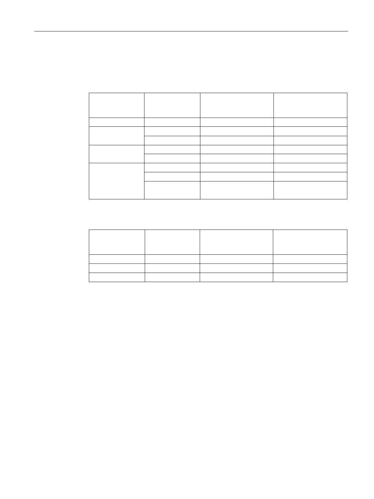
Use the following table and ensure that the CPU and SB input channels that you connect
can support the maximum pulse rates in your process signals:
Table 10- 9 CPU input: maximum frequency
Operating phase: Single
phase or Two phase
Operating phase: A/B
counter or A/B Counter
fourfold
1212C Ia.0 to Ia.5 100 kHz 80 kHz
1214C and 1215C
1217C
Ib.2 to Ib.5
1 MHz 1 MHz
Table 10- 10 SB signal board input: maximum frequency (optional board)
Operating phase: Single
phase or Two phase
Operating phase: A/B
counter or A/B Counter
fourfold
When assigning an input point to an HSC function, you can assign the same input point to
multiple HSC functions. For example, assigning I0.3 to the Sync input of HSC1 and the Sync
input of HSC2 to synchronize the count of both HSCs at the same time is a valid
configuration; however, it generates a compiler warning.

 Loading...


