Installation
4.3 Installation and removal procedures
S7-1200 Programmable controller
62 System Manual, V4.2, 09/2016, A5E02486680-AK
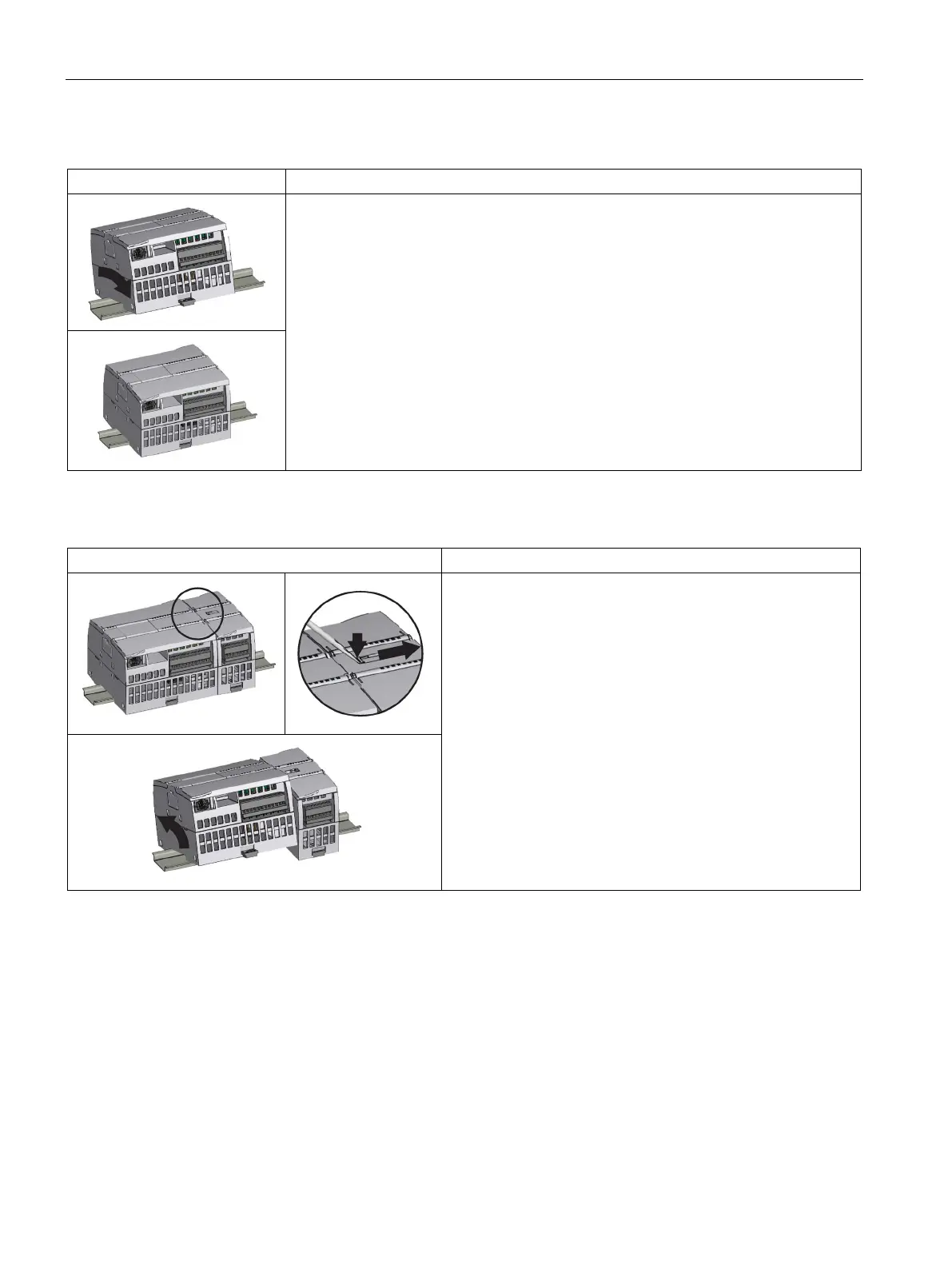
Table 4- 2 Installing the CPU on a DIN rail
1. Install the DIN rail. Secure the rail to the mounting panel every 75 mm.
2. Ensure that the CPU and all S7-1200 equipment are disconnected from electrical
power.
3. Hook the CPU over the top of the DIN rail.
4. Pull out the DIN rail clip on the bottom of the CPU to allow the CPU to fit over the rail.
5. Rotate the CPU down into position on the rail.
6. Push in the clips to latch the CPU to the rail.
Table 4- 3 Removing the CPU from a DIN rail
1. Ensure that the CPU and all S7-1200 equipment are dis-
connected from electrical power.
2. Disconnect the I/O connectors, wiring, and cables from the
CPU (Page 68).
3.
Remove the CPU and any attached communication modules
as a unit. All signal modules should remain installed.
4. If an SM is connected to the CPU, retract the bus connector:
– Place a screwdriver beside the tab on the top of the sig-
nal module.
– Press down to disengage the connector from the CPU.
– Slide the tab fully to the right.
5. Remove the CPU:
– Pull out the DIN rail clip to release the CPU from the rail.
– Rotate the CPU up and off the rail, and remove the CPU
from the system.

 Loading...


