Installation
4.4 Wiring guidelines
S7-1200 Programmable controller
System Manual, V4.2, 09/2016, A5E02486680-AK
81
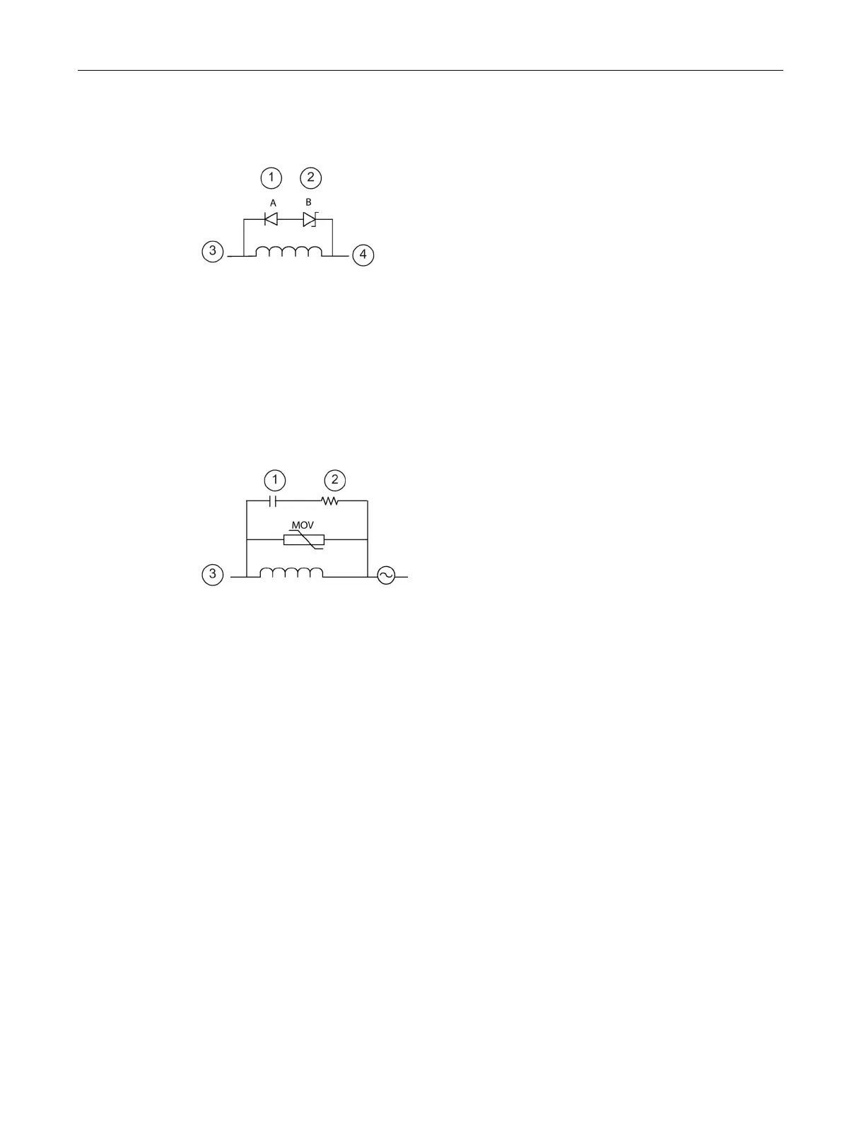
Typical suppressor circuit for DC or relay outputs that switch DC inductive loads
In most applications, the addition of a diode (A)
across a DC inductive load is suitab
le, but if your
application requires faster turn
-off times, then the
addition of a zener diode (B) is recommended. Be
sure to size your zener diode properly for the amount
of current in your output circuit.
1N4001 diode or equivalent
②
outputs),
36 V Zener (Relay outputs)
Typical suppressor circuit for relay outputs that switch AC inductive loads
Ensure that the working voltage of the metal oxide
varistor (MOV) is at lea
st 20% greater than the nomi-
-rated, non-inductive resistors, and
capacitors recommended for pulse applications (typ
i-
cally metal film). Verify the components meet ave
r-
age power, peak power, and peak voltage
requirements.

 Loading...


