RM0440 Rev 4 1829/2126
RM0440 Serial audio interface (SAI)
1858
40.5 SAI registers
The peripheral registers have to be accessed by words (32 bits).
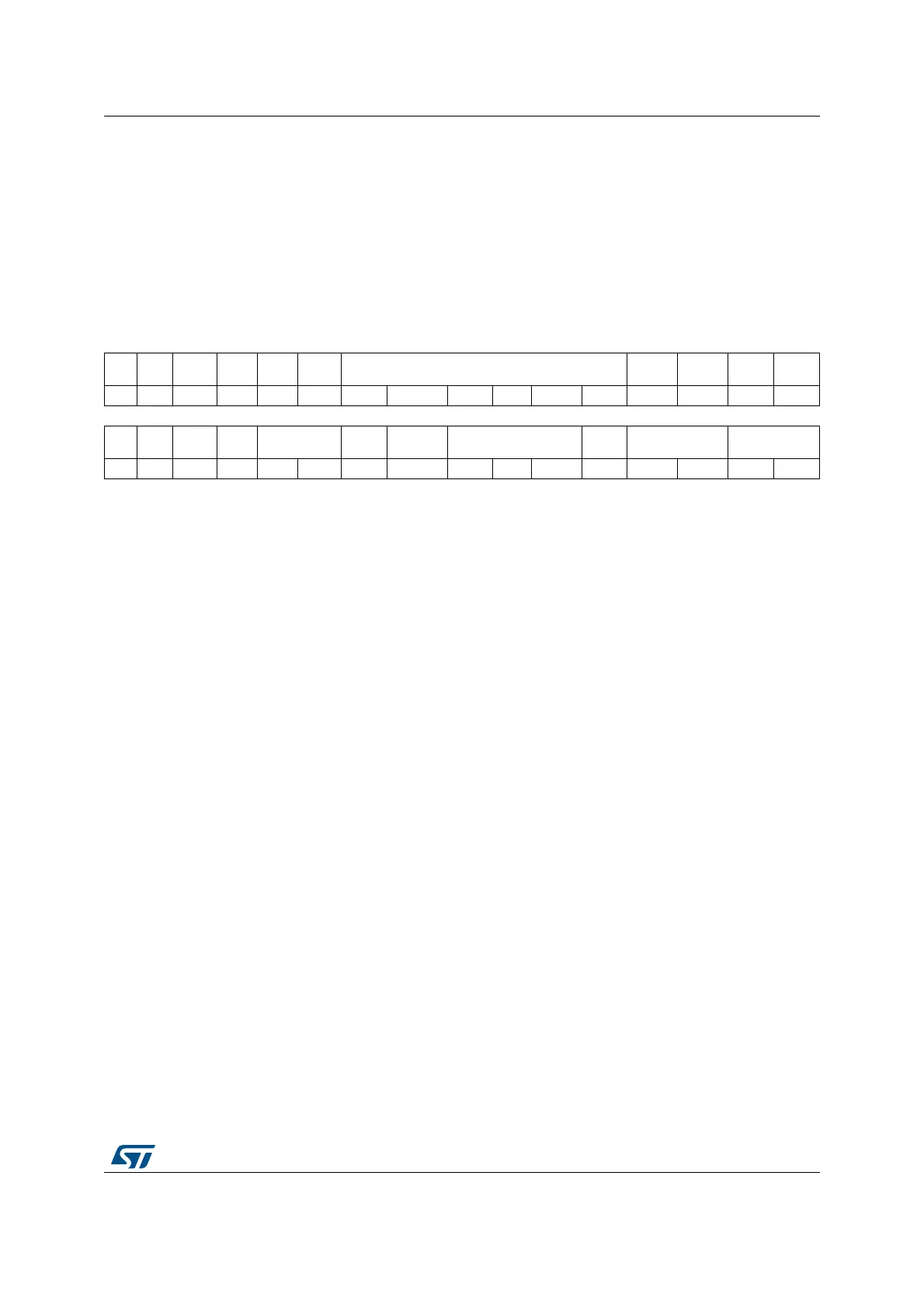
40.5.1 SAI configuration register 1 (SAI_ACR1)
Address offset: 0x004
Reset value: 0x0000 0040
31 30 29 28 27 26 25 24 23 22 21 20 19 18 17 16
Res. Res. Res. Res.
MCK
EN
OSR MCKDIV[5:0] NODIV Res. DMAEN SAIEN
rw rw rw rw rw rw rw rw rw rw rw
15 14 13 12 11 10 9 8 7 6 5 4 3 2 1 0
Res. Res.
OUTD
RIV
MONO SYNCEN[1:0] CKSTR LSBFIRST DS[2:0] Res. PRTCFG[1:0] MODE[1:0]
rw rw rw rw rw rw rw rw rw rw rw rw rw
Bits 31:28 Reserved, must be kept at reset value.
Bit 27 MCKEN: Master clock generation enable
0: The master clock is not generated
1: The master clock is generated independently of SAIEN bit
Bit 26 OSR: Oversampling ratio for master clock
This bit is meaningful only when NODIV bit is set to 0.
0: Master clock frequency = F
FS
x 256
1: Master clock frequency = F
FS
x 512
Bits 25:20 MCKDIV[5:0]: Master clock divider
These bits are set and cleared by software.
000000: Divides by 1 the kernel clock input (sai_x_ker_ck).
Otherwise, The master clock frequency is calculated according to the formula given in
Section 40.3.8: SAI clock generator.
These bits have no meaning when the audio block is slave.
They have to be configured when the audio block is disabled.
Bit 19 NODIV: No divider
This bit is set and cleared by software.
0: the ratio between the Master clock generator and frame synchronization is fixed to 256 or 512
1: the ratio between the Master clock generator and frame synchronization depends on FRL[7:0]
Bit 18 Reserved, must be kept at reset value.
Bit 17 DMAEN: DMA enable
This bit is set and cleared by software.
0: DMA disabled
1: DMA enabled
Note: Since the audio block defaults to operate as a transmitter after reset, the MODE[1:0] bits must
be configured before setting DMAEN to avoid a DMA request in receiver mode.

 Loading...