RM0440 Rev 4 959/2126
RM0440 High-resolution timer (HRTIM)
1083
27.5 HRTIM registers
27.5.1 HRTIM master timer control register (HRTIM_MCR)
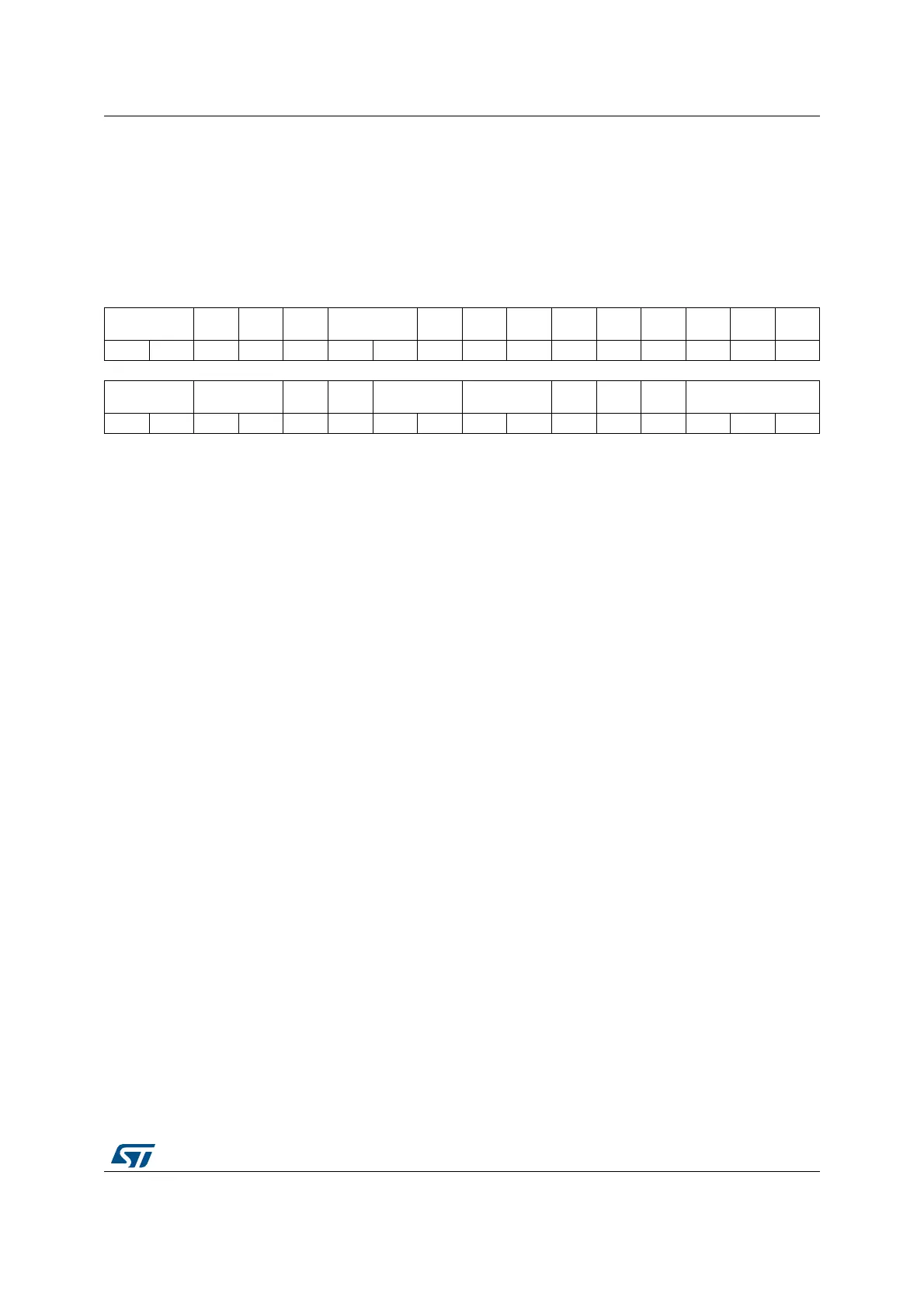
Address offset: 0x000
Reset value: 0x0000 0000
31 30 29 38 27 26 25 24 23 22 21 20 19 18 17 16
BRSTDMA[1:0]
MREP
U
Res. PREEN DACSYNC[1:0] Res. Res. TFCEN TECEN TDCEN TCCEN TBCEN TACEN MCEN
rw rw rw rw rw rw rw rw rw rw rw rw rw
1514131211109876543210
SYNCSRC[1:0] SYNCOUT[1:0]
SYNCS
TRTM
SYNCR
STM
SYNCIN[1:0] INTLVD[1:0] HALF
RE
TRIG
CONT CKPSC[2:0]
rw rw rw rw rw rw rw rw rw rw rw rw rw rw rw rw
Bits 31:30 BRSTDMA[1:0]: Burst DMA update
These bits define how the update occurs relatively to a burst DMA transaction.
00: Update done independently from the DMA burst transfer completion
01: Update done when the DMA burst transfer is completed
10: Update done on master timer roll-over following a DMA burst transfer completion. This mode
only works in continuous mode.
11: Reserved
Bit 29 MREPU: Master timer repetition update
This bit defines whether an update occurs when the master timer repetition period is completed
(either due to roll-over or reset events). MREPU can be set only if BRSTDMA[1:0] = 00 or 01.
0: Update on repetition disabled
1: Update on repetition enabled
Bit 28 Reserved, must be kept at reset value.
Bit 27 PREEN: Preload enable
This bit enables the registers preload mechanism and defines whether the write accesses to the
memory mapped registers are done into HRTIM’s active or preload registers.
0: Preload disabled: the write access is directly done into the active register
1: Preload enabled: the write access is done into the preload register
Bits 26:25 DACSYNC[1:0] DAC synchronization
A DAC synchronization event can be enabled and generated when the master timer update occurs.
These bits are defining on which output the DAC synchronization is sent (refer to Section 27.3.21:
DAC triggers for connections details).
00: No DAC trigger generated
01: Trigger generated on hrtim_dac_trg1
10: Trigger generated on hrtim_dac_trg2
11: Trigger generated on hrtim_dac_trg3
Bits 24:23 Reserved, must be kept at reset value.
Bit 22 TFCEN: Timer F counter enable
This bit starts the timer F counter.
0: Timer F counter disabled
1: Timer F counter enabled
Note: This bit must not be changed within a minimum of 8 cycles of f
HRTIM
clock.
 Loading...


