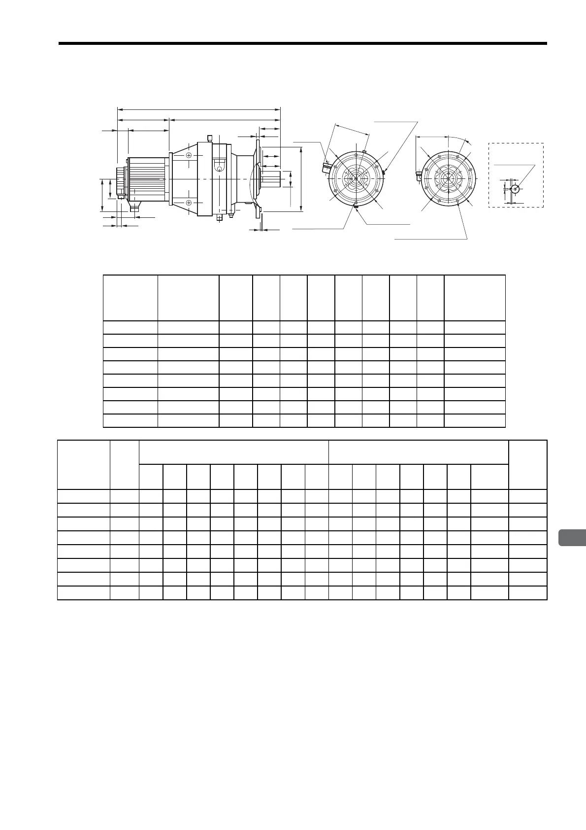
3.16 Dimensional Drawings of SGMGH Servomotors (1000 min
-1
)
3-111
3
Servomotor Specifications and Dimensional Drawings
(3) Large Oil Lubricating Type
Q
LG
LR
LE
R
QK
KB1
22
KL1
88
LM
45
LL
L
φSh6
φLBf8
22.5q
φLC
φLA
N-φLZ
Mounting holes
Oil drain plug
Oil filler
plug
Oil drain plug
A
φLC
φLA
N-φLZ Mounting holes
* See the following
table.
8 Mounting holes6 Mounting holes
A
W
T
U
Tap × Depth*
Shaft End
Units: mm
Model
SGMGH-
Gear Model
Gear
Ratio
L LL LM KB1 KL1 R A
Shaft Center
Allowable
Radial Load
N
20PBF76 CHVJ-6160
1/29 687 192 147 77 140 495 228 20500
30PBFC6 CHVJ-6160
1/21 721 226 181 77 140 495 228 18600
30PBF76 CHVJ-6170
1/29 785 226 181 77 140 559 243 23100
40PBFC6 CHVJ-6170
1/21 853 260 215 86 150 593 243 21000
40PBF76 CHVJ-6175
1/29 853 260 215 86 150 593 243 23000
55PBFB6 CHVJ-6160
1/11 863 334 289 86 150 529 228 15000
55PBFC6 CHVJ-6175
1/21 927 334 289 86 150 593 243 20900
55PBF76 CHVJ-6185
1/29 977 334 289 86 150 643 258 30400
Model
SGMGH-
Gear
Ratio
Flange Face Dimensions
mm
Shaft-end Dimensions
mm
Approx.
Mass
kg
LA LB LC LE LG LR N LZ Q QK S T U W
Tap
×
Depth
20PBF76
1/29 310 270 340 4 20 89 6 11 90 80 60 11 7 18
M10
×18
121
30PBFC6
1/21 310 270 340 4 20 89 6 11 90 80 60 11 7 18
M10
×18
126
30PBF76
1/29 360 316 400 5 22 94 8 14 90 80 70 12 7.5 20
M12×24
176
40PBFC6
1/21 360 316 400 5 22 94 8 14 90 80 70 12 7.5 20
M12
×24
191
40PBF76
1/29 360 316 400 5 22 94 8 14 90 80 70 12 7.5 20
M12
×24
191
55PBFB6
1/11 310 270 340 4 20 89 6 11 90 80 60 11 7 18
M10×18
150
55PBFC6
1/21 360 316 400 5 22 94 8 14 90 80 70 12 7.5 20
M12
×24
201
55PBF76
1/29 390 345 430 5 22 110 8 18 110 100 80 14 9 22
M12
×24
232

 Loading...


