8 Operation
8.3.4 Setting for Holding Brakes
8-24
Note: The above operation delay time is an example when the power supply is turned ON
and OFF on the DC side.
Be sure to evaluate the above times on the actual equipment before using the application.
1. The brake built into the servomotor with brakes is a deenergization brake, which is used only to hold and
cannot be used for braking. Use the holding brake only to hold a stopped motor. Brake torque is at least
120% of the rated motor torque.
2. When operating using only a speed loop, turn OFF the servo and set the input reference to 0 V when the
brake is applied.
3. When forming a position loop, do not use a mechanical brake while the servomotor is stopped because
the servomotor enters servolock status.
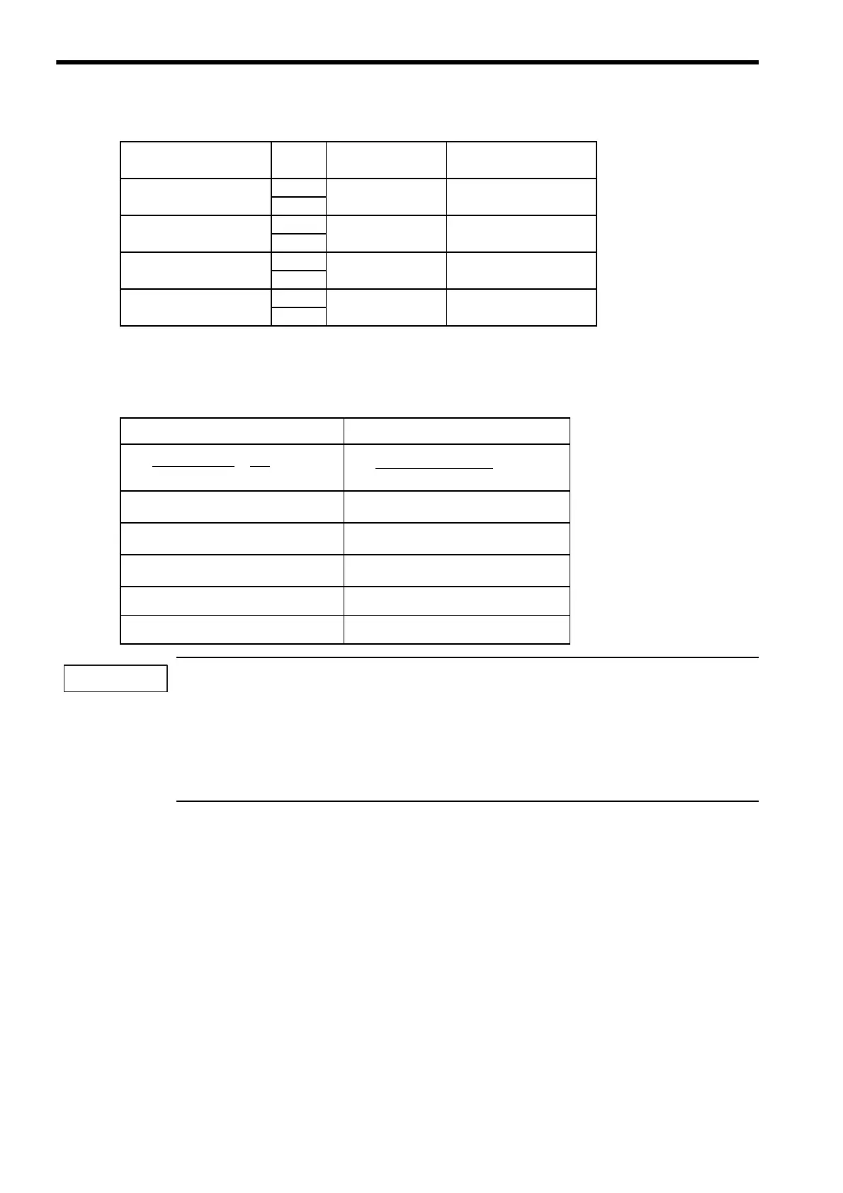
SGMSH-50
90 V 100 80
24 V
SGMDH-22
90 V 170 80
24 V
SGMDH-32
90 V 170 80
24 V
SGMDH-40
90 V 170 80
24 V
Table 8.2 Calculation Method for Servomotor Stop Time
Using SI Units Conventional Method
J
M
: Rotor moment of inertia (kgxm
2
) GD
2
M
: Motor GD
2
(kgfxm
2
)
J
L
: Load moment of inertia (kgxm
2
) GD
2
L
: Load inertia GD
2
(kgfxm
2
)
N
M
: Motor rotational speed (min
-1
)
N
M
: Motor rotational speed (r/min)
T
P
: Motor deceleration torque (Nxm) T
P
: Motor deceleration torque (kgfxm)
T
L
: Load torque (Nxm) T
L
: Load torque (kgfxm)
Table 8.1 Brake Operation Delay Time (Cont’d)
Model Voltage
Brake Open Time
(ms)
Brake Operation Time
(ms)
t
0
= × (sec)
(T
P
+ T
L
)
(J
M
+ J
L
) × N
M
2π
60
t
0
= (sec)
(GD
2
M
+ GD
2
L
) × N
M
375 × (T
P
+ T
L
)

 Loading...


