8.3 Setting Common Basic Functions
8-25
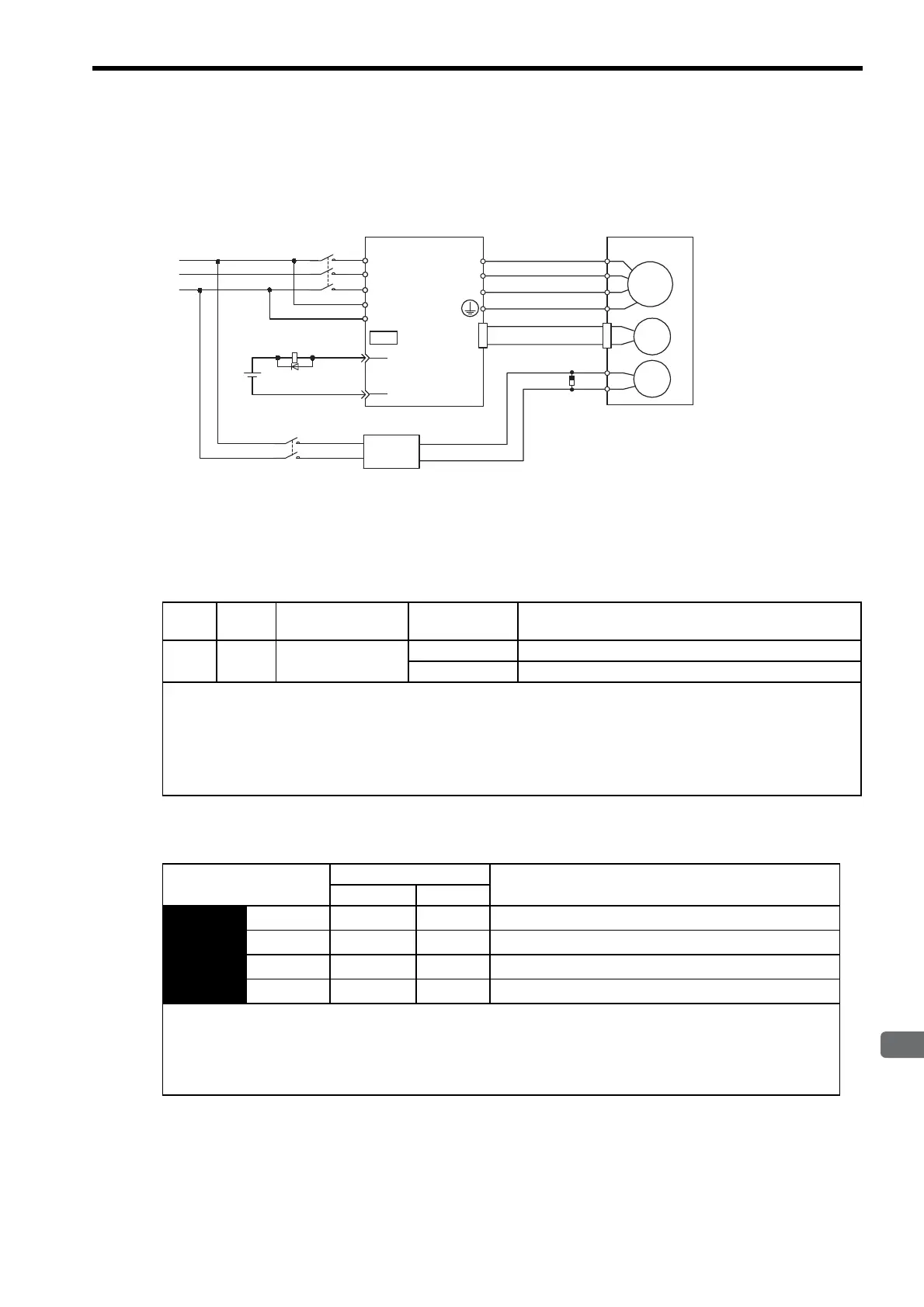
(1) Wiring Example
Use the SERVOPACK contact output signal /BK and the brake power supply to form a brake ON/OFF circuit.
The following diagram shows a standard wiring example.
(2) Brake Interlock Output
(3) Allocating Brake Signals (/BK)
The brake signal (/BK) is not used with the factory settings. The output signal must be allocated.
Servomotor
with brake
SERVOPACK
Power supply
Red
Black
Blue or
yellow
White
BK-R Y
: Brake control relay
∗
1 and
∗
2 are the output terminals allocated with Pn50F.2.
M
BK
PG
U
V
W
CN2
AC DC
BK-RY
BK-RY
+24V
L1
L2
L3
L1C
L2C
(/BK+)
(/BK-)
CN1
∗1
∗2
Brake power supply
Brake power supply Input voltage 200-V models: LPSE-2H01
Input voltage 100-V models: LPDE-1H01
R
S
T
Surge absorber
CR50500BL
(manufactured by
Okaya Electric
Industries Co., Ltd.)
Type Name Connector Pin
Number
Setting Meaning
Output /BK Must be allocated ON (low level) Releases the brake.
OFF (high level) Applies the brake.
This output signal controls the brake and is used only for a servomotor with a brake. This output signal is not used with the
factory settings. The output signal must be allocated (with Pn50F). It does not need to be connected for servomotors with-
out a brake.
IMPORTANT
The /BK signal is not output during overtravel, or when there is no power to the servomotor.
Parameter Connector Pin Number Meaning
+ Terminal - Terminal
Pn50F
n.
0
−−The /BK signal is not used. (Factory setting)
n.
1
CN1-25 CN1-26 The /BK signal is output from output terminal CN1-25, 26.
n.
2
CN1-27 CN1-28 The /BK signal is output from output terminal CN1-27, 28.
n.
3
CN1-29 CN1-30 The /BK signal is output from output terminal CN1-29, 30.
IMPORTANT
When set to the factory setting, the brake signal is invalid. When multiple signals are allocated to the same output termi-
nal, the signals are output with OR logic. To output the /BK signal alone, disable the other output signals or set them to
output terminals other than the one allocated to the /BK signal. For the allocation of SERVOPACK output signals other
than /BK signal, refer to 7.3.3 Output Circuit Signal Allocation.

 Loading...


