12 Appendix
12.3.2 List of Parameters
12-32
* This setting must be changed only for special applications. Changing this limit inappropriately or unintentionally
can be dangerous.
Parameter
No.
Name Setting Range Unit
Factory
Setting
Setting
Validation
Reference
Section
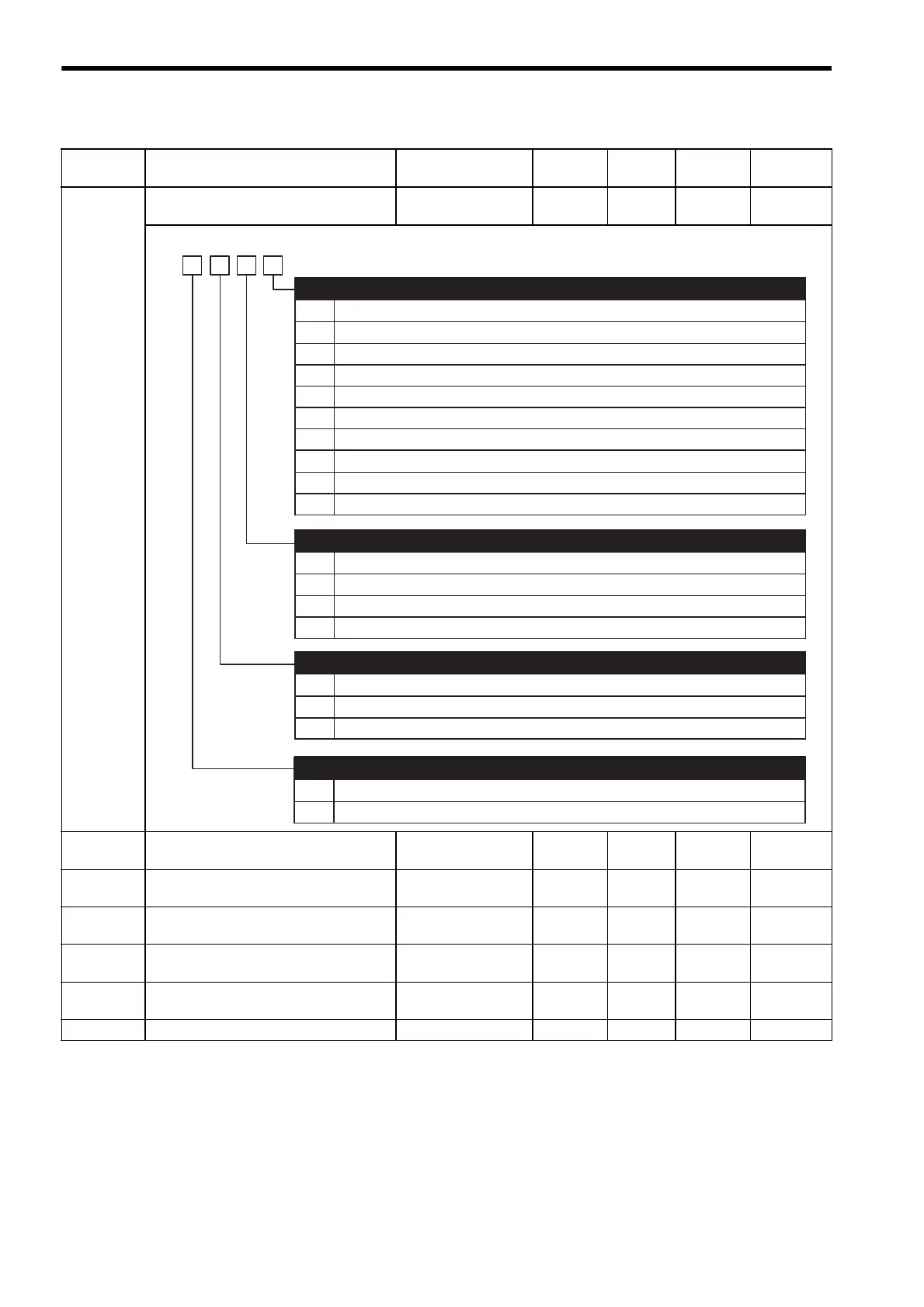
Pn200 Position Control References Selection
Switches
−−0000 After
restart
8.6.1
Pn201 PG Dividing Ratio
(For 16-bit or less)
16 to 16384 1 P/rev 16384 After
restart
8.5.7
Pn202 Electronic Gear Ratio (Numerator)
1 to 65535 − 4After
restart
8.6.2
Pn203 Electronic Gear Ratio (Denominator)
1 to 65535 − 1After
restart
8.6.2
Pn204 Position Reference Accel/Decel Time
Constant
0 to 6400 0.01 ms 0 Immedi-
ately
8.6.4
Pn205 Multiturn Limit Setting *
0 to 65535 1 rev 65535 After
restart
8.4.7
Pn206 Reserved (Do not change)
−−16384 −−
0
1
2
3
4
5
6
7
8
9
Sign + Pulse, positive logic
CW + CCW, positive logic
Phase A + Phase B ( ×1), positive logic
Phase A + Phase B ( ×2), positive logic
Phase A + Phase B ( ×4), positive logic
Sign + Pulse, negative logic
CW + CCW, negative logic
Phase A + Phase B ( ×1), negative logic
Phase A + Phase B ( ×2), negative logic
Phase A + Phase B ( ×4), negative logic
Reference Pulse Form
0
1
2
3
Clears error counter when the signal is at H level.
Clears error counter at the rising edge of the signal.
Clears error counter when the signal is at L level.
Clears error counter at the falling edge of the signal.
Error Counter Clear Signal From
4th
digit
3rd
digit
2nd
digit
1st
digit
n.
0
1
2
Clears error counter at the baseblock.
Does not clear error counter (Possible to clear error counter only with CLR signal).
Clears error counter when an alarm occurs.
Clear Operation
0
1
Reference input filter for line driver signals
Reference input filter for open collector signals
Filter Selection

 Loading...


