12 Appendix
12.3.2 List of Parameters
12-40
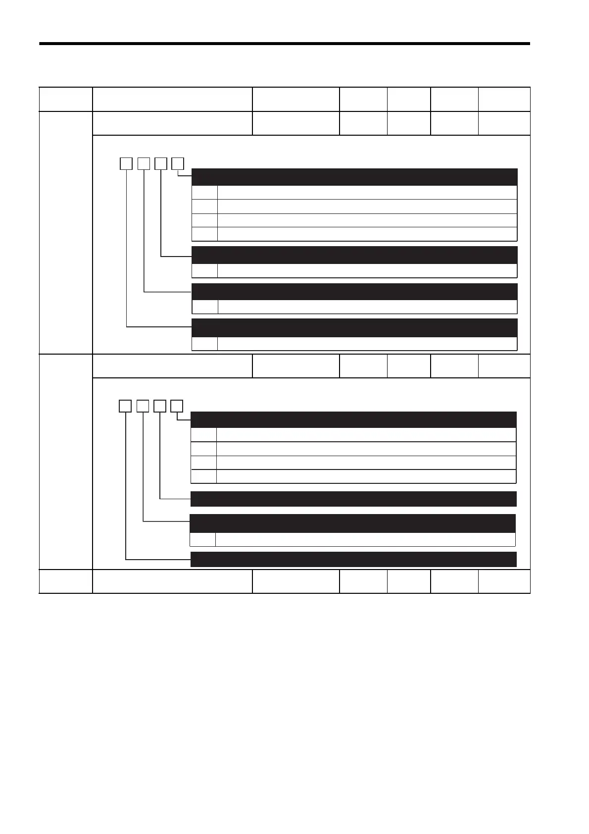
Pn50F Output Signal Selections 2
−−0000 After
restart
−
Pn510 Output Signal Selections 3
0000 to 0333 − 0000 After
restart
−
Pn511 Reserved (Do not change)
−−8888 Immedi-
ately
−
* Used only when the software version is 32 or later.
Parameter
No.
Name Setting Range Unit
Factory
Setting
Setting
Validation
Reference
Section
0
1
2
3
0 to 3
Disabled (the above signal is not used.)
Outputs the signal from CN1-25, -26 output terminal.
Outputs the signal from CN1-27, -28 output terminal.
Outputs the signal from CN1-29, -30 output terminal.
Same as /CLT
Same as /CLT
Same as /CLT
Torque Limit Detection Signal Mapping (/CLT)
(Refer to "8.9.5 Checking Output Torque Limiting during Operation.")
Speed Limit Detection Signal Mapping (/VLT)
(Refer to "8.7.4 Limiting Servomotor Speed during Torque Control.")
Brake Interlock Signal Mapping (/BK)
(Refer to "8.3.4 Setting for Holding Brakes.")
4th
digit
3rd
digit
2nd
digit
1st
digit
n.
0 to 3
0 to 3
Warning Signal Mapping (/WARN)
(Refer to "8.11.2 Warning Output (/WARN).")
0
1
2
3
Disabled (the above signal is not used.)
Outputs the signal from CN1-25 or -26 terminals.
Outputs the signal from CN1-27 or -28 terminals.
Outputs the signal from CN1-29 or -30 terminals.
Near Signal Mapping (/NEAR)
(Refer to "8.6.6 Positioning Near Signal.")
4th
digit
3rd
digit
2nd
digit
1st
digit
n.
Reserved (Do not change)
Reserved (Do not change)
Same as /NEAR
0 to 3
Reference Pulse Input Multiplication Change Output Signal Mapping (/PSELA)
∗
(Refer to "10.3.3 Reference Pulse Input Multiplication Range Switching Function.")

 Loading...


