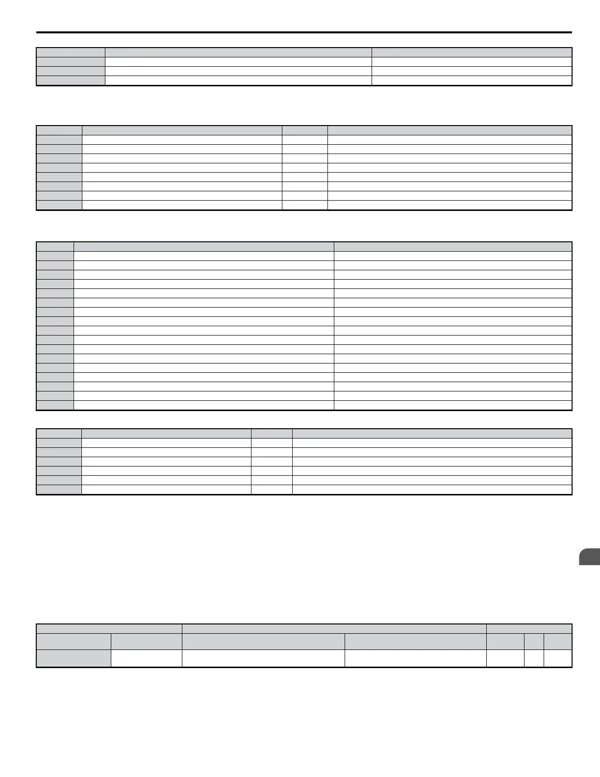
No. Parameter Name Optimum Setting
L8-07 Output Phase Loss Protection 1: Enabled
L8-38 Carrier Frequency Reduction 0: Derated when operating at 6 Hz or less
L8-41 Current Alarm Selection 1: Enabled (alarm is output)
Note: 1. A sequence to release the hold brake is needed for when the multi-function output photocoupler P2-PC closes.
2. Perform Auto-Tuning after selecting the Hoist Application Preset.
Parameters below are automatically saved as Preferred Parameters (A2-01 to A2-16):
No. Parameter Name No. Parameter Name
A1-02 Control Method Selection d1-02 Frequency Reference 2
b1-01 Frequency Reference Selection d1-03 Frequency Reference 3
b6-01 Dwell Reference at Start E1-08 Mid Output Frequency Voltage (VC)
b6-02 Dwell Time at Start H2-01 Terminals MA, MB, and MC Function Selection
C1-01 Acceleration Time 1 L1-01 Motor Overload Protection Selection
C1-02 Deceleration Time 1 L4-01 Speed Agreement Detection Level
C6-02 Carrier Frequency Selection L6-02 Torque Detection Level 1
d1-01 Frequency Reference 1 L6-03 Torque Detection Time 1
Note: Read the instructions listed in Notes on Using the Hoist Application Preset when using the Hoist Application Preset.
7: Crane Application: Parameters and Settings
No. Parameter Name Optimum Setting
A1-02 Control Mode 0: V/f Control
b1-01 Frequency Reference Selection 0: Operator
C1-01 Acceleration Time 1 3.0 s
C1-02 Deceleration Time 1 3.0 s
C6-01 Duty Cycle 0: Heavy Duty
C6-02 Carrier Frequency Selection 2: 5 kHz
d1-01 Frequency Reference 1 6.0 Hz
d1-02 Frequency Reference 2 30.0 Hz
d1-03 Frequency Reference 3 60.0 Hz
H1-05 Multi-Function Digital Input Terminal S5 Function 3: Multi-Step Speed 1
H1-06 Multi-Function Digital Input Terminal S6 Function 4: Multi-Step Speed 2
H2-02 Terminals P1 Function Selection (open-collector) 37: During frequency output
L3-04 Stall Prevention Selection during Decel 0: Disabled
L8-05 Input Phase Loss Protection Selection 1: Enabled
L8-07 Output Phase Loss Protection 1: Triggered when a single phase is lost
L8-38 Carrier Frequency Reduction 1: Always derated
L8-41 Current Alarm Selection 1: Enabled (alarm output)
Parameters below are automatically saved as Preferred Parameters (A2-01 to A2-16):
No. Parameter Name No. Parameter Name
b1-01 Frequency Reference Selection d1-03 Frequency Reference 3
C1-01 Acceleration Time 1 E2-01 Motor Rated Current
C1-02 Deceleration Time 1 H1-05 Multi-Function Digital Input Terminal S5 Function
C6-02 Carrier Frequency Selection H1-06 Multi-Function Digital Input Terminal S6 Function
d1-01 Frequency Reference 1 H2-01 Terminals MA, MB, and MC Function Selection
d1-02 Frequency Reference 2 L1-01 Motor Overload Protection Selection
Note: A sequence to release the hold brake is needed for when the multi-function output photocoupler P2-PC closes.
n
Notes on Using the Hoist Application Preset
This section lists some important points when using the Hoist Application Preset (A1-06 = 6).
Opening and Closing the Holding Brake
Conditions
Use an output signal as described below to operate the holding brake in a hoist application.
• Set frequency detection so it does not operate during baseblock (L4-07 = 0). Even when an external baseblock command is present, the output frequency
will rise when a run command is entered. If frequency detection were to be enabled during baseblock (i.e., if L4-07 = 1), then the brake would be
improperly released.
To activate and release the brake using the multi-function output terminals P1-PC, program the drive as shown in the table below:
Brake Open/Close Brake Activation Level Control Mode
Function Parameter Signal Parameter V/f OLV
OLV for
PM
Frequency Detection 2
L4-07 = 0
H2-02 = 5
Frequency Detection Level
Frequency Detection Width
L4-01 = 1.0 to 3.0 Hz
*1
L4-02 = 0.0 to 0.5 Hz
*2
O O −
*1. This is the setting range available when using Open Loop Vector Control. In V/f Control, set the level as the motor rated slip frequency pulse 0.5 Hz. Not enough motor torque will be
created if this value is set too low, and the load may tend to slip. Make sure this value is greater than the minimum output frequency and greater than the value of L4-02 as shown in the
diagram below. If set too high, however, there may be a jolt at start.
5.1 A: Initialization
YASKAWA ELECTRIC SIEP C710606 18A YASKAWA AC Drive – V1000 Technical Manual (Preliminary)
107
5
Parameter Details

 Loading...


