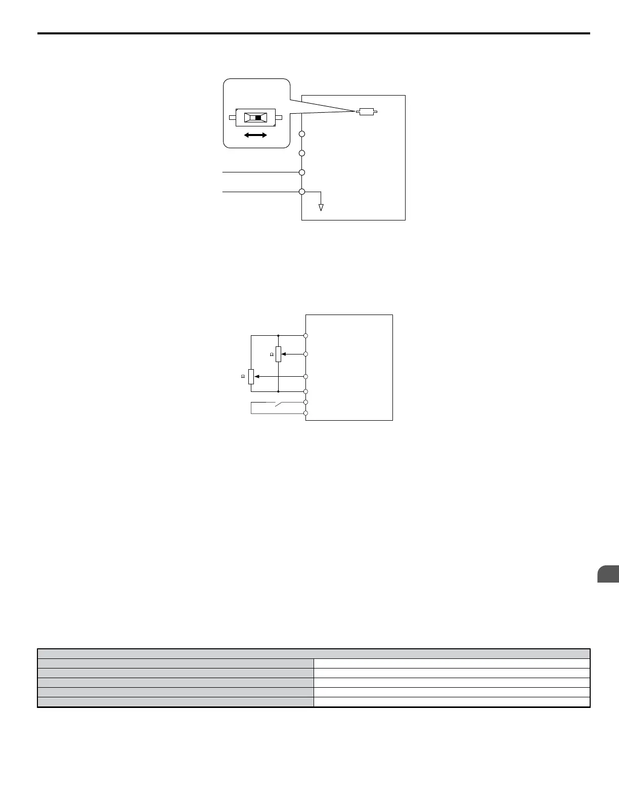
• Set the signal level for multi-function analog input terminal A2 to accept a 4 to 20 mA signal (H3-09 = 2), and the gain for input terminal A2 to 0
(H3-10 = 0)
• For a current signal input, DIP switch S1 must be set to the “I” position. For a voltage signal input, DIP switch S1 must be set to the “V” position.
Drive
A1
A2
Frequency reference
(voltage input)
Frequency reference bias
(voltage or current input)
AC
Frequency reference common
+V (+10.5 V, 20 mA power supply)
4 to 20 mA input
DIP switch S1
V I
Figure 5.3 Supplying the Frequency Reference with a Current Input
• Switching between Main/Aux Frequency References
When using the main/aux frequency reference for a two-step speed sequence, input the main frequency reference to terminal A1 and the auxiliary
frequency reference to terminal A2. When the multi-function input terminal that has been set for Multi-Step Speed Reference 1 (the default setting for
terminal S5) is open, the frequency reference for the drive is supplied by terminal A1. When the contact closes, the frequency reference for the drive
changes to terminal A2. When using terminal A2 for an auxiliary frequency reference, set the multi-function analog input terminal A2 function for
“Aux Frequency Reference 1” (H3-10 = 2).
Drive
A1
A2
Frequency Reference
(voltage input)
Frequency Reference Bias
AC
S5
Frequency Reference Common
Multi-Function Digital Input
SC
Sequence Input Common
+ V (+10.5 V, 20 mA power supply)
2 k
(voltage input)
2 k
Switching between Frequency References
Note: When using multi-function analog input terminal A2 to enter the frequency reference with a voltage signal, the current/voltage DIP switch on the drive needs to be set to
voltage. Parameter H3-09 also needs to be set to “1”, which will allows terminal A2 to accept a voltage signal of 0 to 10 V.
2: MEMOBUS/Modbus Communications
To supply the frequency reference via serial communications, set b1-01 to “2” (Serial Com), and connect the RS-485/422 serial communications cable
to terminals R+, R-, S+, and S- on the control I/O terminal block.
3: Option card
Set b1-01 to “3” (Option PCB) and plug a communication option board into the 2CN port on the drive control PCB. Consult the manual supplied with
the option board for instructions on integrating the drive with the communication system.
Note: If the frequency reference source is set for an option PCB (b1-01 = 3), but an option board is not installed in 2CN, an OPE05 Operator Programming Error will be displayed
on the digital operator and the drive will not run.
4: Pulse Train Input
Setting b1-01 to 4 tells the drive that the frequency reference will be provided by the Pulse Train input, located at control circuit terminal RP.
Verifying Pulse Train is Working Properly
• With H6-02 (Pulse Train Input Scaling) at its default setting of 1440 Hz, manually rotate the pulse generator and see how much the frequency reference
increases.
• If the frequency reference does not reach 60 Hz, check the value of H6-02 (Pulse Train Input Scaling).
• Set the Pulse Train to provide the frequency reference (H6-01 = 0) and put the Pulse Train scaling (H6-02) at 100%.
Pulse Train Input Specifications
Response Frequency 0.5 to 33 kHz
Heavy Duty 30 to 70%
High Level Voltage 3.5 to 13.2 V
Low Level Voltage 0.0 to 0.8 V
Input Impedance 3 kΩ
5.2 b: Setup
YASKAWA ELECTRIC SIEP C710606 18A YASKAWA AC Drive – V1000 Technical Manual (Preliminary)
111
5
Parameter Details

 Loading...


