No. Parameter Name Setting Range Default
b5-15 PID Sleep Function Start Level 0.0 to 400.0 0.0
b5-16 PID Sleep Delay Time 0.0 to 25.5 0.0
Detailed Description
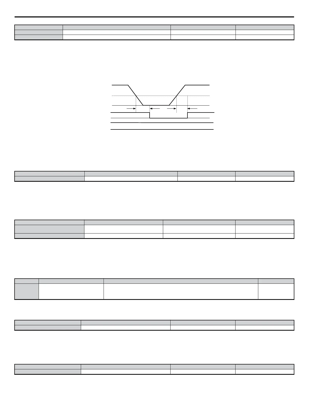
• If the conditions that triggered the PID Sleep function continue and output fails to rise above the PID Sleep level, the drive will coast to stop.
• If the PID output rises above the PID Sleep level, the drive will automatically be restarted even though the PID Sleep delay time has not fully passed.
• PID Sleep is always enabled, even when PID control is disabled.
Note: Select the stopping method for the drive when PID Sleep is activated.
The figure below illustrates what happens when PID Sleep is triggered.
PID Output
PID Sleep Function
Trigger Point ( b5-15)
Sleep Delay Time Sleep Delay Time
Run Command Enabled
Continues to Output “During Run”
Internal Run
Command
External Run
Command
During Run
Stop
b5-16 b5-16
Run
Figure 5.18 PID Sleep
n
b5-17: PID Accel/Decel Time
This is a soft start function that is applied to the PID setpoint analog input. Instead of having nearly instantaneous changes in signal levels, there is a
programmed ramp applied to level changes. When changing setpoints the error can be limited by gradually ramping the setpoint through the use of
parameter b5-17.
No. Parameter Name Setting Range Default
b5-17 PID Accel/Decel Time 0 to 255 0
Note: Depending on the settings, resonance with the PID control and hunting in the machinery may occur because the acceleration and deceleration times set to the C1 parameters
are allocated after PID control. Parameter b5-17 can be use to prevent such problems. The PID Soft Starter function can also be disabled or enabled by setting one of the multi-
function digital inputs to 34.
n
b5-18: PID Setpoint Selection
n
b5-19: PID Setpoint Value
No. Parameter Name Setting Range Default
b5-18 PID Setpoint Selection
0: Disabled
1: Enabled
0
b5-19 PID Setpoint Value 0.00 to 100.00 0.00
Sets the PID target value. Use only when b5-18 = 1.
If b5-18 = “0: Disabled”, then the PID Setpoint will either be the Modbus register 06H (provided register 0FH bit 1 is high), or the active frequency
reference.
n
b5-20: PID Setpoint Scaling
Determines the units that the PID setpoint (b5-19) is set in and displayed. Also determines the units for monitors U5-01 and U5-04.
No. Parameter Name Setting Range Default
b5-20 PID Setpoint Scaling
0: 0.01 Hz units
1: 0.01% units (100% of max output frequency)
2: r/min (set the motor poles)
3: User-set display (set using b5-38 and b5-39)
1
n
b5-34: PID Output Lower Limit
Sets the minimum output possible from the entire PID controller.
No. Parameter Name Setting Range Default
b5-34 PID Output Lower Limit -100.0 to 100.0 0.00
• Set as a percentage of the maximum frequency (E1-04).
• The lower limit is disabled when set to 0.0%.
n
b5-35: PID Input Limit
If the input value for PID control is high, the output will also be high. This parameter limits the input value.
No. Parameter Name Setting Range Default
b5-35 PID Input Limit 0 to 1000.0 1000.0
5.2 b: Setup
128
YASKAWA ELECTRIC SIEP C710606 18A YASKAWA AC Drive – V1000 Technical Manual (Preliminary)

 Loading...


