EasyManuals Logo

YASKAWA V1000 Series Technical Manual

YASKAWA V1000 Series
372 pages
To Next Page IconTo Next Page
To Previous Page IconTo Previous Page
Page #138 background imageLoading...
Page #138 background image
*K is a coefficient determined by the value of C6-03. C6-03 greater than or equal to 10.0 kHz: K=3 10.0 kHz > C6-03 greater than or equal to 5.0 kHz:
K=2 5.0 kHz > C6-03: K=1
Note: A carrier frequency error (oPE11) will occur when the carrier frequency proportional gain is greater than 6 while C6-03 is less than C6-04.
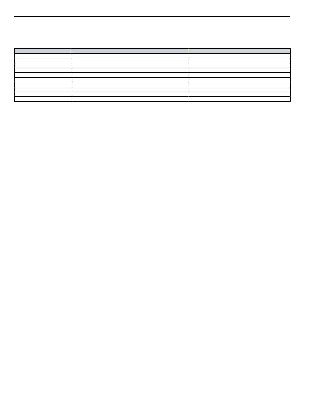
Table 5.2 Carrier Frequency Default Values
CIMR-Vo
C6-02: Carrier Frequency Selection C6-03: Carrier Frequency Upper Limit (kHz)
Single-Phase 200 V Class: Normal Duty Rating (ND)
B0001 7 (Swing PWM1) 2.0
B0002 7 (Swing PWM1) 2.0
B0003 7 (Swing PWM1) 2.0
B0006 7 (Swing PWM1) 2.0
B0010 7 (Swing PWM1) 2.0
B0012 7 (Swing PWM1) 2.0
B0020 7 (Swing PWM1) 2.0
Single-Phase 200 V Class: Heavy Duty Rating (HD)
B0001 4 (10.0 kHz) 10.0
5.3 C: Tuning
138
YASKAWA ELECTRIC SIEP C710606 18A YASKAWA AC Drive – V1000 Technical Manual (Preliminary)

Table of Contents

Other manuals for YASKAWA V1000 Series

Questions and Answers:

Question and Answer IconNeed help?

Do you have a question about the YASKAWA V1000 Series and is the answer not in the manual?

YASKAWA V1000 Series Specifications

General IconGeneral
ModelV1000 Series
SeriesV1000
Output Frequency0.1 to 400 Hz
Overload Capacity150% for 60 seconds
TypeAC Drive
Control MethodV/f Control
Input Voltage200-240V, 380-480V
Output Voltage0 to Input Voltage
Power Range0.1 to 18.5 kW
Horsepower0.2 to 25 HP
Protection FeaturesOvercurrent, Overvoltage, Undervoltage, Overheating, Short Circuit, Ground Fault
Communication InterfacesModbus RTU
EnclosureIP20
Ambient Temperature-10 to +50°C
Storage Temperature-20 to +60°C
Humidity5 to 95% RH (non-condensing)
Cooling MethodFan Cooled

Related product manuals