Function F: Not Used
Any digital input that is not used or is used as through-put should be set to F. This way drive operation will not be affected by the switch, whether it is
open or closed.
Setting 10: Up Command
Setting 11: Down Command
Using two digital inputs, the drive can operate with the same type of functionality as a motor operated potentiometer (MOP). One digital input can be
programmed as the Up input (H1-0x= 10) to increase the frequency reference, and another digital input can be programmed as the Down input (H1-0x=
11) to decrease the frequency reference. To use these functions, the source of the frequencyr reference must be assigned to the terminals (b1-02 = 1).
Status Description
Open Maintain the present frequency reference (no effect)
Closed Increase or decrease the frequency reference
An opE03 error will occur under the following conditions, indicating that there is a contradictory setting among the functions assigned to terminals S1 to
S7:
• The Up function cannot be programmed without also programming the Down function (or vice-versa)
• UP/DOWN function is assigned to the terminals while the Accel/Decel Ramp Hold function is also programmed into other digital inputs
No. Parameter Name Setting Range Default Page
d2-01 Frequency Reference Upper Limit 0.0 to 110.0 100.0% −
d2-02 Frequency Reference Lower Limit 0.0 to 110.0 0.0% −
d2-03 Master Speed Reference Lower Limit 0.0 to 110.0 0.0% −
E1-04 Max Output Frequency (FMAX) 40.0 to 400.0* 60.0 Hz* −
When using PM Open Loop Vector Control, these settings will change according to the motor code set to E5-01.
Note: Once the Up/Down functions are programmed, the preset speeds are disabled and the analog frequency reference input becomes a potential frequency reference lower limit.
The lower limits for Up/Down are the greater of the analog frequency reference and the programmed frequency reference lower limit (d2-03). The upper limit will be d2-01
(Frequency Reference Upper Limit).Once a Run command is issued the drive will accelerate immediately to the lower limit. When Up/Down functions are not used, the upper
limit is the maximum output frequency (E1-04).The status of the d4-01 parameter will affect the performance of the drive after power is cycled to the drive and a fresh Run
command is issued. If d4-01= “0: Disabled”, the Run command will cause the drive to ramp to the frequency reference lower limit. However, if d4-01= “1: Enabled”, the Run
command will cause the drive to ramp to the last frequency referenced by the Up/Down function before the Run command was removed and the power cycled. Even if d4-01=
“1: Enabled”, the previous frequency reference can be reset to the frequency reference lower limit automatically by closing either the Up or Down input without having a Run
command active.
No. Parameter Name Setting Range Default Page
d4-01
Frequency Reference Hold Function
Selection
0: Disabled. Drive starts the motor with a frequency reference of 0 if the power is
interrupted.
1: Enabled. Drive starts the motor at the frequency reference that was saved just before
the power went out.
0 −
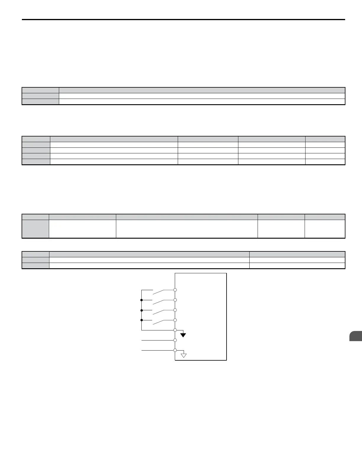
Below is an example of drive operation when the Up function is assigned to terminal S3 and the Down function to terminal S4.
No. Parameter Name Setting
H1-03 Multi-Function Digital Input Terminal S3 Function Selection 10: Up Command
H1-04 Multi-Function Digital Input Terminal S3 Function Selection 11: Down Command
DRIVE
0 t o +10 V
analog signal
S1 FWD/Stop
S2 REV/Stop
S3 Up command
S4 Down command
SC sequence common
A1 Frequency reference
lower limit
AC
Figure 5.40 Up/Down Functions and Terminal Assignments
5.7 H: Terminal Functions
YASKAWA ELECTRIC SIEP C710606 18A YASKAWA AC Drive – V1000 Technical Manual (Preliminary)
163
5
Parameter Details

 Loading...


