By configuring one of the digital inputs as an Integral Reset Input, (H1-0o = 30), the value of the integral component of PID control can be reset to 0
whenever the configured input is closed. The integral component of PID control will be held at 0 as long as the configured digital input is held closed.
Note: For more informatin on PID control,
Refer to b5: PID Control on page 122.
Setting 31: PID Integral Hold
By configuring a digital input for Integral Hold (H1-0o = 31), the value of the integral component of the PID control can be forced to clamp at the value
it was at when the input is closed. The integral component of the PID control returns to accumulating the error when the digital input is open again.
Holding the integral value can be useful during periods when the error can build up naturally, such
Note: For more informatin on PID control,
Refer to b5: PID Control on page 122.
Function 32: Multi-Step Speed 4
For more details, see the descriptions for setting functions 3, 4, and 5 on page
161.
Function 34: PID SFS Cancel
By configuring a digital input as a PID SFS Cancel input (H1-0o = 34), the operator will be able to use a contact closure to remove the acceleration and
deceleration times that are applied to changes in the PID setpoint by the b5-17 parameter. If the digital input configured as PID SFS Cancel is closed, the
PID setpoint accel/decel set to b5-17 will be disregarded.
Note: For more informatin on PID control,
Refer to b5: PID Control on page 122.
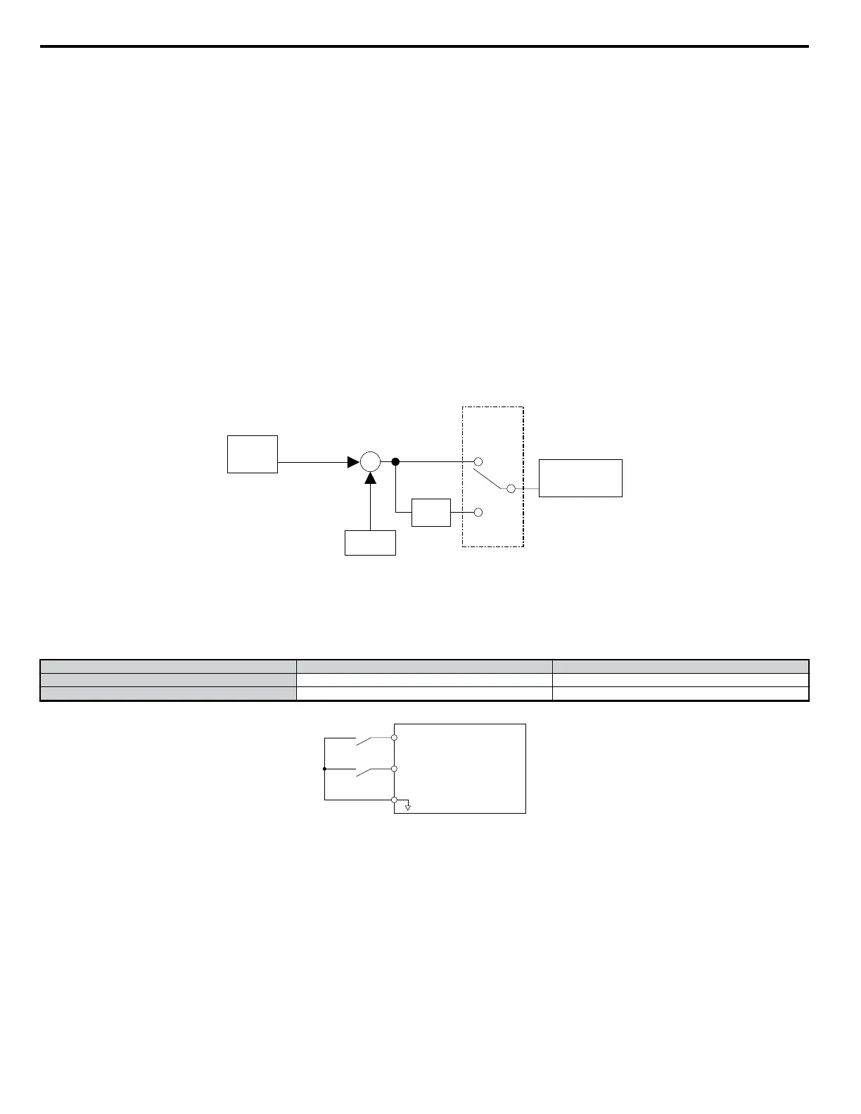
Function 35: PID Input Level Selection
When using the PID Function built into the drive, the set point that has been selected is compared with the feedback that was measured. The difference
is called the error. The proportional and integral function are applied to this error. For some applications it may be appropriate to invert the input to the
PID block. This can be accomplished by setting one of the digital inputs up as an Input Level Selection (H1-0o = 35). When the terminal for the input
level is closed, the error will be inverted before it is passed to the PID block.
+
-
Set
Point
Feedback
Closed
H1=0x=35
Open
PID Block
-
1
Figure 5.45 PID Input Characteristics
Setting 40: Forward Run Command (2-Wire Sequence)
Setting 41: Reverse Run Command (2-Wire Sequence)
Assigns a 2-wire sequence to the input terminals so that a forward or reverse Run command is issued when the contacts close.
Control Circuit Terminal Closed Open
S1 Forward Run Stop
S2 Reverse Run Stop
S1
S2
SC
Drive
Digital Input Common
Forward Run
Reverse Run
Figure 5.46 2-Wire Sequence Wiring Diagram
Note: Settings 42 and 43 cannot be simultaneously set to the multi-function input terminals.
Setting 42: 2-Wire Sequence 2 (Run Command)
Setting 43: 2-Wire Sequence 2 (Forward/Reverse Command 2)
Sets up a 2-wire sequence to the input terminals. One of the terminals executes the Run command when closed, while the other determines the direction
of the Run command: forward when closed, reverse when open.
Note: Settings 40 and 41 cannot be simultaneously set to the multi-function input terminals.
Setting 44: Offset Frequency 1 Addition
Setting 45: Offset Frequency 2 Addition
Setting 46: Offset Frequency 3 Addition
Operates much the same as a bias. When the input is switched on, the value set to d7-01, d7-02, and d7-03 are added to the frequency reference.
Note: For more information,
Refer to d7: Offset Frequencies on page 144.
5.7 H: Terminal Functions
168
YASKAWA ELECTRIC SIEP C710606 18A YASKAWA AC Drive – V1000 Technical Manual (Preliminary)

 Loading...


