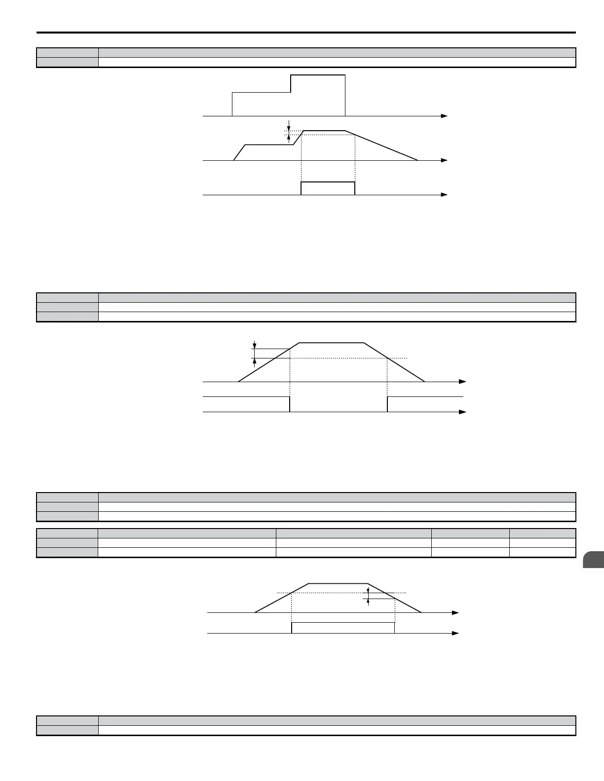
Status Description
Closed Output frequency and the frequency reference are both equal to L4-01 ± hysteresis for L4-02
L4-02
Frequency Detection Level
(L4-01)
Speed Agree Detection Width
TIME
Output Frequency
Speed Agree Signal
Frequency Reference
Figure 5.52 User-Set Speed Agree Timing Diagram
Setting 4: Frequency Detection 1
Output closes whenever the output frequency is equal to or below the value of the programmed Speed Agreement Level (L4-01). The Speed Agreement
Width (L4-02) is the hysteresis to Frequency Detection 1.
Status Description
Open Drive is stopped or the condition described below is not true
Closed Frequency Detection 1 > (+L4-01 greater than or equal to output frequency greater than or equal to -L4-01, L4-02)
Note: The terminal opens when the output for Frequency Detection 1 reaches the level set to L4-01. Frequency Detection 1 can also be used when the motor is rotating in reverse.
L4-02
L4-01
a - Speed Agree Width (L4-02)
TIME
Output Frequency
Frequency
Detection 1 Signal
Figure 5.53 Frequency Detection 1 Timing Diagram
Setting 5: Frequency Detection 2
Output closes whenever the output frequency is equal to or above the value of the programmed Speed Agreement Level (L4-01). The Speed Agreement
Width (L4-02) is the hysteresis to Frequency Detection 2.
Status Description
Open Drive is stopped or the condition described below is not true
Closed Frequency Detection 1 > (+L4-01 greater than or equal to output frequency greater than or equal to -L4-01, L4-02)
No. Parameter Name Setting Range Default Page
L4-01 Frequency Detection Level 0.0 to 400.0 0.0 Hz −
L4-02 Frequency Detection Width 0.0 to 20.0 2.0 Hz −
Note: The output terminal set for Frequency Detection 2 will close when the output frequency falls below the level set to L4-01 minus the Speed Agree detection width set to L4-02.
Frequency Detection 2 can also be used when the motor is rotating in reverse.
L4-02
L4-01
Speed Agree detection width
time
output frequency
Frequenccy
Detection 2
signal
Figure 5.54 Frequency Detection 2 Timing Diagram
Setting 6: Drive Ready
Output closes whenever the drive is not in a fault state and not being programmed. If b1-08 = 1: Enabled”, a drive that is in an active Run state that is also
being programmed will have the Drive Ready output closed.
Status Description
Open Processing: Drive is powering up, initializing parameter settings, dealing with a fault situation, or in the Programming Mode.
5.7 H: Terminal Functions
YASKAWA ELECTRIC SIEP C710606 18A YASKAWA AC Drive – V1000 Technical Manual (Preliminary)
173
5
Parameter Details

 Loading...


