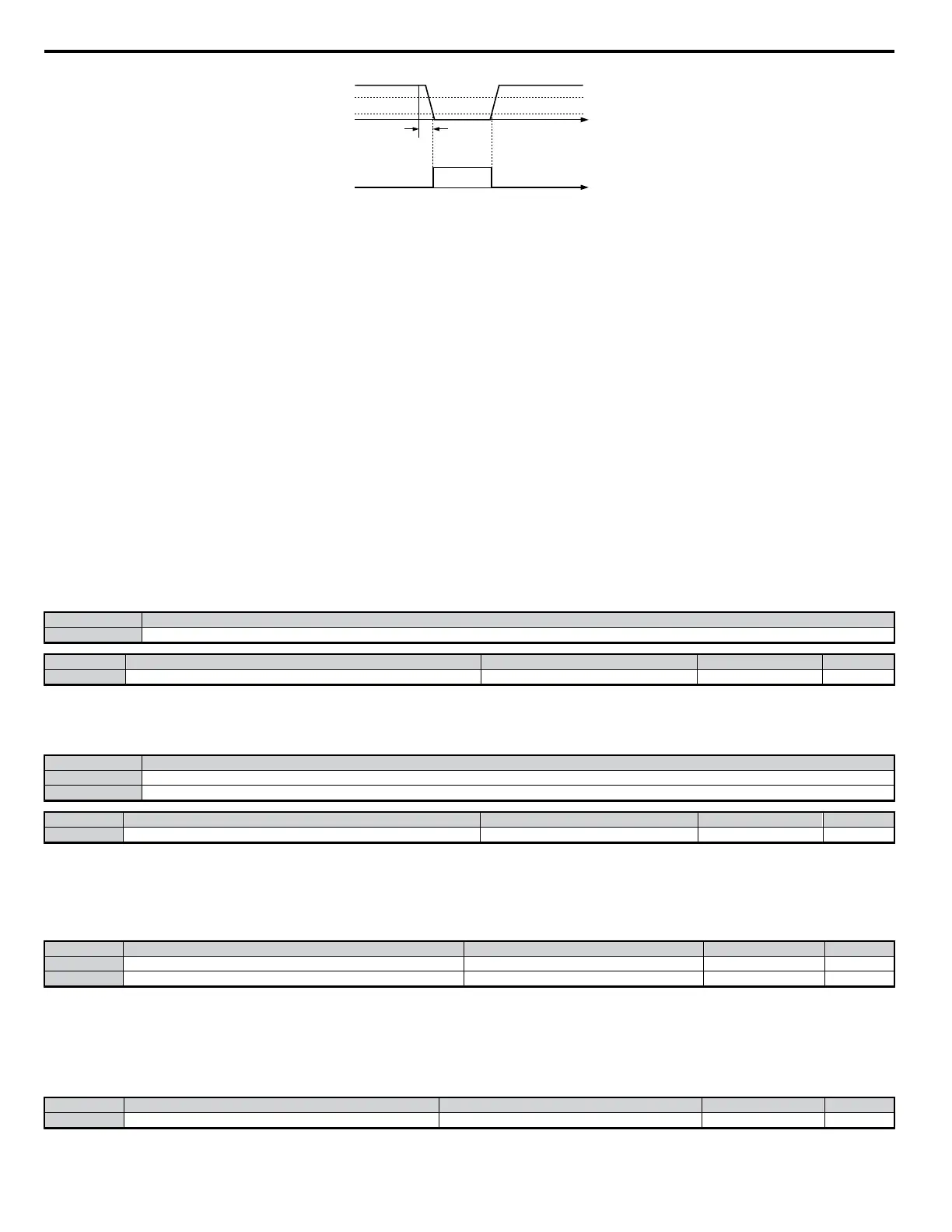
100%
T
analog
frequency
reference
Loss of
Reference
output
time
80%
10%
T = 400 ms
ON
OFF
Figure 5.57 Loss of Reference Function
Setting D: Dynamic Braking Resistor Overheat
When the dynamic braking resistor (DB) overheats or the braking transistor is in a fault condition, the DB Overheat configured digital output will close.
Setting E: Fault
The Fault configured digital output will close whenever the drive experiences a fault (this excludes faults CPF00 and CPF01).
Setting F: Not Used
Use this setting when the terminal is not used or when using the terminal as a through-put.
Setting 10: Minor Fault
Output closes when a minor fault condition is present.
Setting 11: During Fault Reset
Output closes whenever there is an attempt to reset a fault situation from the control circuit terminals, via serial communications, or using a communications
option card.
Setting 12: Timer Output
Used in conjunction with a multi-function digital input programmed for the timer function. Output closes after the input closes and the time set to b1-04
pass.
Note: For more information on the various timer functions,
Refer to b4: Delay Timers on page 122
Setting 13: Speed Agree 2
Output closes whenever the output frequency is equal to or below the value of the programmed Speed Agree Level. The Speed Agree Width (L4-04) is
the hysteresis to Frequency Detection 2.
Status Description
Closed Output currents matches the frequency reference +/- L4-04
No. Parameter Name Setting Range Default Page
L4-04 Speed Agreement Detection Width (+/-) 0.0 to 20.0 2.0 Hz −
Setting 14: User Speed Agree 2
Output closes whenever the actual output frequency and the frequency reference are within the Speed Agree Width (L4-04) of the specified Speed Agree
Level (L4-03). User Speed Agree 2 output is direction sensitive according to the direction programmed in L4-03.
Status Description
Open Output frequency and the frequency reference do not match (or the drive is stopped).
Closed Output currents matches the frequency reference +/- L4-04
No. Parameter Name Setting Range Default Page
L4-04 Speed Agreement Detection Width (+/-) 0.0 to 20.0 2.0 Hz −
Setting 15: Frequency Detection 3
Output will be closed whenever the output frequency is equal to or below the value of the specified Speed Agree Level (L4-03). The Speed Agree Width
(L4-04) is the hysteresis to the Frequency Detection 3 function. Whenever the output frequency approaches the Speed Agree Level while accelerating, it
will need to be equal to or exceed the Speed Agree Level (L4-03) plus the Speed Agree Width (L4-04) before the Frequency Detection 3 output will be
activated.
No. Parameter Name Setting Range Default Page
L4-03 Speed Agreement Detection Level (+/-) -400.0 to 400.0 0.0 Hz −
L4-04 Speed Agreement Detection Width (+/-) 0.0 to 20.0 2.0 Hz −
Note: During acceleration, the terminal set for Frequency Detection 3 will close if the output frequency is greater than the frequency detection level (L4-03) and the frequency
detection width (L4-04). During deceleration, the terminal set for Frequency Detection 3 will close as long as the output frequency is less than the frequency detection level
(L4-03). The output for Frequency Detection 3 is direction sensitive according to the direction programmed in L4-03.
Setting 16: Frequency Detection 4
Output closes whenever the output frequency is equal to or above the value of the specified Speed Agree Level (L4-03). The Speed Agree Width (L4-04)
is the hysteresis to the Frequency Detection 4 function.
No. Parameter Name Setting Range Default Page
L4-03 Speed Agreement Detection Level (+/-) -400.0 to 400.0 0.0 Hz −
5.7 H: Terminal Functions
176
YASKAWA ELECTRIC SIEP C710606 18A YASKAWA AC Drive – V1000 Technical Manual (Preliminary)

 Loading...


