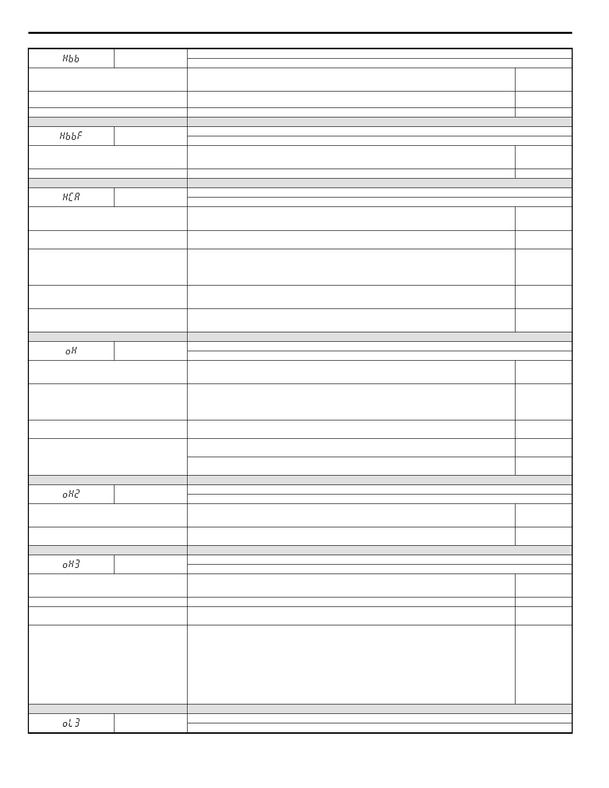
Hbb
Hardwire Baseblock Signal Input
Hardwire Baseblock input signal open.
Cause Possible Solutions
Minor Fault
Output
(H2-
oo = 10)
Internally, both Hardwire Baseblock channels are
broken.
Replace the drive. YES
There is no signal at terminal H1. Check the wiring of terminal H1. Check if the PLC signal is set correctly. YES
LED Operator Display Minor Fault Name
HbbF
Hardwire Baseblock Signal Input
One of the baseblock channels is damaged.
Cause Possible Solutions
Minor Fault
Output
(H2-
oo = 10)
One of the baseblock channels is faulty. Replace the drive. YES
LED Operator Display Minor Fault Name
HCA
Current Alarm
Drive current exceeded overcurrent warning level (150% of the rated current).
Cause Possible Solutions
Minor Fault
Output
(H2-
oo = 10)
Load is too heavy.
• Measure the current flowing through the motor.
• Reduce the load or increase the capacity of the drive.
YES
Acceleration and deceleration times are too short.
• Calculate the torque required during acceleration and for the inertia moment.
• If the torque level is not right for the load, take the following steps:
• Increase the acceleration and deceleration times (C1-01 through C1-08).
• Increase the capacity of the drive.
YES
A special-purpose motor is being used, or the drive is
attempting to run a motor greater than the maximum
allowable capacity.
• Check the motor capacity.
• Use a motor appropriate for the drive. Ensure the motor is within the allowable capacity range.
YES
The current level increased due to Speed Search after a
momentary power loss or while attempting to perform a
fault restart.
The alarm will appear only briefly. There is no need to take action to prevent the alarm from occurring in such instances. YES
LED Operator Display Minor Fault Name
oH
Heatsink Overheat
The temperature exceeded the maximum allowable value.
Cause Possible Solutions
Minor Fault
Output
(H2-
oo = 10)
Surrounding temperature is too high
• Check the surrounding temperature.
• Improve the air circulation within the enclosure panel.
• Install a fan or air conditioner to cool surrounding area.
• Remove anything near drive that may cause extra heat.
YES
Internal cooling fan has stopped.
• Replace the cooling fan. Refer to Cooling Fan Replacement on page 261.
• After replacing the drive, reset the cooling fan maintenance parameter to (o4-03 = “0”).
YES
Airflow around the drive is restricted.
• Provide proper installation space around the drive as indicated in the manual. Refer to Figure 2.1 on page 26.
• Allow for the specified space and ensure that there is sufficient circulation around the control panel.
YES
• Check for dust or foreign materials clogging cooling fan.
• Clear debris caught in the fan that restricts air circulation.
YES
LED Operator Display Minor Fault Name
oH2
Drive Overheat Warning
“Drive Overheat Warning” was input to a multi-function input terminal, S1 through S7 (H1-oo
Cause Possible Solutions
Minor Fault
Output
(H2-
oo = 10)
An external device triggered and overheat warning in the
drive.
• Search for the device that tripped the overheat warning.
• Solving the problem will clear the warning.
YES
LED Operator Display Minor Fault Name
oH3
Motor Overheat
The motor overheat signal entered to a multi-function analog input terminal exceeded the alarm level (H3-02 or H13-10 = E).
Cause Possible Solutions
Minor Fault
Output
(H2-
oo = 10)
Motor thermostat wiring is fault (PTC input). Repair the PTC input wiring. YES
There is a fault on the machine side (e.g., the machine is
locked up).
• Check the status of the machine.
• Remove the cause of the fault.
Motor has overheated.
• Check the load size, accel/decel times, and cycle times.
• Decrease the load.
• Increase accel and decel times (C1-01 to C1-08).
• Adjust the preset V/f pattern (E1-04 through E1-10). This will mainly involve reducing E1-08 and E1-10. Note:
Do not lower E1-08 and E1-10 excessively, because this reduces load tolerance at low speeds.
• Check the motor-rated current.
• Enter motor-rated current on motor nameplate (E2-01).
• Ensure the motor cooling system is operating normally.
• Repair or replace the motor cooling system.
YES
LED Operator Display Minor Fault Name
oL3
Overtorque 1
Drive output current (or torque in OLV) was greater than L6-02 for longer than the time set in L6-03.
6.5 Alarm Detection
240
YASKAWA ELECTRIC SIEP C710606 18A YASKAWA AC Drive – V1000 Technical Manual (Preliminary)

 Loading...


