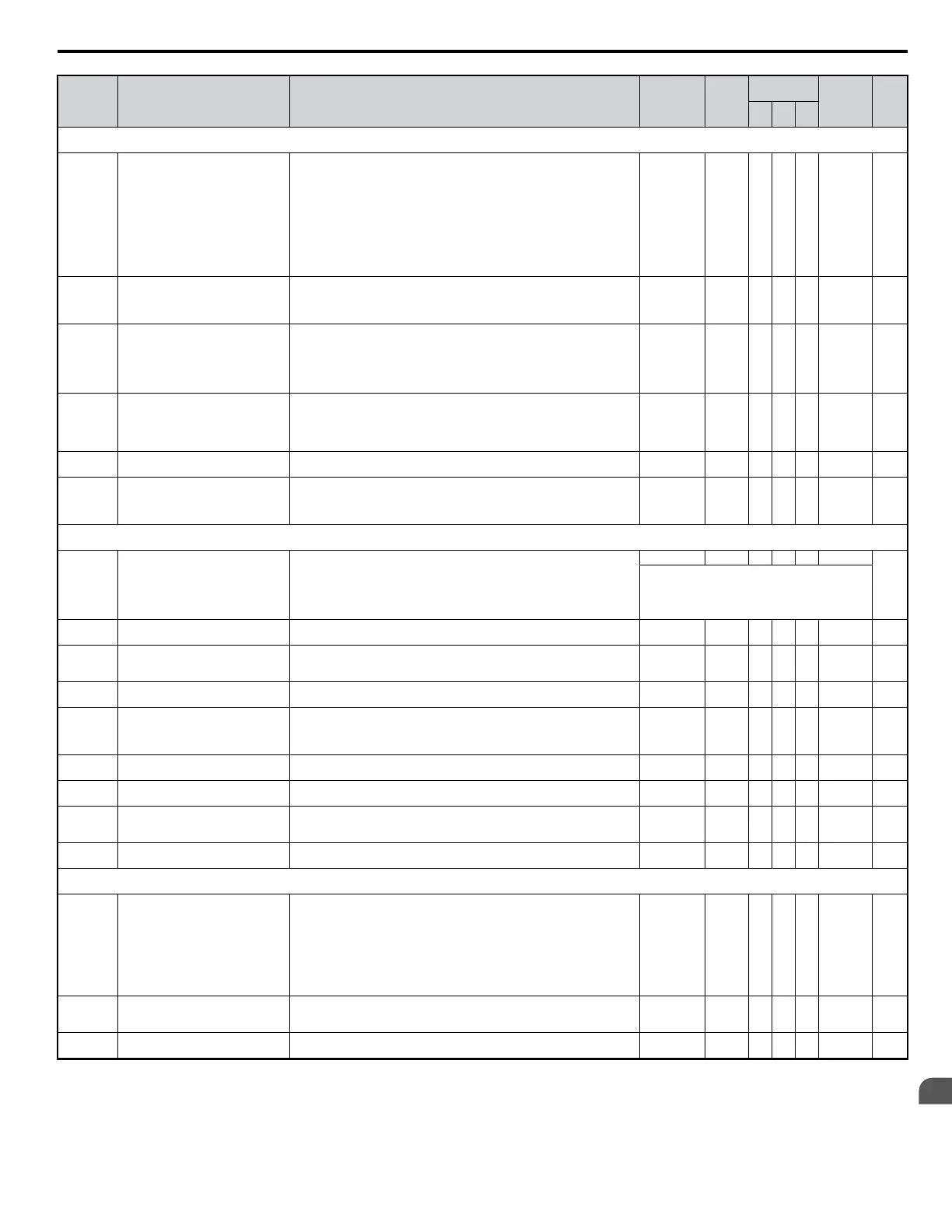
No. Name Description Range Def.
Control
Mode
Addr.
Hex
Pg.
V/f
OL
V
PM
L1: Motor Protection Functions
Use L1 parameters to configure motor protective functions.
L1-01 Motor Overload Protection Selection
Sets the motor thermal overload protection (OL1) based on the cooling capacity
of the motor.
0: Disabled
1: Standard Fan Cooled (< 10:1 motor)
2: Standard Blower Cooled (≥ 10:1 motor)
3: Vector Motor (100:1 motor)
4: PM motor with variable torque
NOTICE: The thermal protection is reset when the power is cycled. In
applications where the power is frequently cycled, the drive may not be able to
provide protection, even if this parameter is set to 1. Set to “0” and ensure each
motor has a thermal relay installed.
0 to 4 1 <2> S S S 480 87
L1-02 Motor Overload Protection Time
Sets the motor thermal overload protection (OL1) time.
A larger L1-02 time will increase the time for an OL1 fault to occur.
This parameter does not typically require adjustment. Should be set in accordance
with the overload tolerance of the motor.
0.1 to 5.0 1.0 min A A A 481 —
L1-03
Motor Overheat Alarm Operation
Selection (PTC input)
Sets operation when the motor temperature analog input (H3-02/10 = E) exceeds
the OH3 alarm level.
0: Ramp to Stop
1: Coast to Stop
2: Fast-stop using C1-09
3: Alarm Only (“oH3” will flash)
0 to 3 3 A A A 482 —
L1-04
Motor Overheat Fault Operation
Selection (PTC input)
Sets stopping method when the motor temperature analog input (H3-02/10 = E)
exceeds the OH4 fault level.
0: Ramp to Stop
1: Coast to Stop
2: Fast-stop
0 to 2 1 A A A 483 —
L1-05
Motor Temperature Input Filter Time
(PTC input)
This parameter adjusts the filter on the motor temperature analog input (H3-02
or H3-10 = E). Increase to add stability, decrease to improve response.
0.00 to 10.00 0.20 s A A A 484 —
L1-13
Continuous Electrothermal Operation
Selection
Determines whether or not to hold the electrothermal value when the power
supply is interrupted.
0: Disabled
1: Enabled
0 to 1 1 A A A 46D —
L2: Momentary Power Loss
Use L2 parameters to configure drive functions for momentary power loss conditions.
L2-01
Momentary Power Loss Operation
Selection
Enables and disables the momentary power loss function.
0: Disabled - Drive trips on (UV1) fault when power is lost.
1: Power Loss Ride-Thru Time - Drive will restart if power returns within the
time set in L2-02.
2: CPU Power Active - Drive will restart if power returns as long as the CPU is
working.
0 to 2 0 A A A 485
—
For a restart to occur, the run command must be
maintained throughout the ride-thru period.
L2-02
Momentary Power Loss Ride-Thru
Time
Sets the Power Loss Ride-Thru time. Only effective when L2-01 = 1. 0.0 to 25.5 <12> A A A 486 —
L2-03
Momentary Power Loss Minimum
Baseblock Time
Sets the minimum wait time for residual motor voltage decay before the drive
output reenergizes after power loss ride-thru. If L2-03 is greater than L2-02,
operation resumes after the time set in L2-03.
0.1 to 5.0 <57> A A A 487 —
L2-04
Momentary Power Loss Voltage
Recovery Ramp Time
Sets the time for the output voltage to return to the preset V/f pattern during speed
search.
0.0 to 5.0 <12> A A A 488 —
L2-05 <24>
Undervoltage Detection Level (UV)
Sets the DC Bus undervoltage trip level. If this is set lower than the default setting,
additional AC input impedance or DC bus reactance may be necessary. Consult
with the manufacturer before changing this parameter setting.This value is used
for KEB activation if L2-01 > 0.
150 to 210
<9>
<12>
A A A 489 —
L2-06 KEB Deceleration Time
Sets the time required to decelerate from the speed when KEB was activated to
zero speed.
0.0 to 200.0 0.0 s A A A 48A —
L2-07 KEB Acceleration Time
Set the time to accelerate to the set speed after recovery from a momentary power
loss. If set to 0.0, the active acceleration time is used.
0.0 to 25.5 0.0 s A A A 48B —
L2-08
KEB Start Output Frequency
Reduction
Sets the percentage of output frequency reduction at the beginning of deceleration
when a KEB command is input from multi-function input.
Reduction = (slip frequency before KEB) x L2-08 x 2
0 to 300 100% A A A 48C —
L2-11 <24>
Desired DC Bus Voltage during KEB Sets the desired value of the DC bus voltage during KEB. 150 to 400 V
E1-01 x
1.22
A A A 461 —
L3: Stall Prevention Function
Use L3 parameters to configure the stall prevention function.
L3-01
Stall Prevention Selection during
Acceleration
Selects the stall prevention method used to prevent excessive current during
acceleration.
0: Disabled - Motor accelerates at active acceleration rate. The motor may stall
if load is too heavy or accel time is too short.
1: General Purpose - When output current exceeds L3-02 level, acceleration
stops. Acceleration will continue when the output current level falls below the
L3-02 level.
2: Intelligent - The active acceleration rate is ignored. Acceleration is completed
in the shortest amount of time without exceeding the current value set in L3-02.
0 to 2 <29> 1 A A A 48F —
L3-02
Stall Prevention Level during
Acceleration
Used when L3-01 = 1 or 2.
100% is equal to the drive rated current.
Decrease the set value if stalling or excessive current occurs with default setting.
0 to 150 <7> A A A 490 —
L3-03
Stall Prevention Limit during
Acceleration
Sets stall prevention lower limit during acceleration when operating in the
constant power range. Set as a percentage of the drive's rated current.
0 to 100 50% A A A 491 —
B.2 Parameter Table
YASKAWA ELECTRIC SIEP C710606 18A YASKAWA AC Drive – V1000 Technical Manual (Preliminary)
311
B
Parameter List

 Loading...


