No. Name Description Range Def.
Control
Mode
Addr.
Hex
Pg.
V/f
OL
V
PM
L7: Torque Limit
Use L7 parameters to configure the torque limit function.
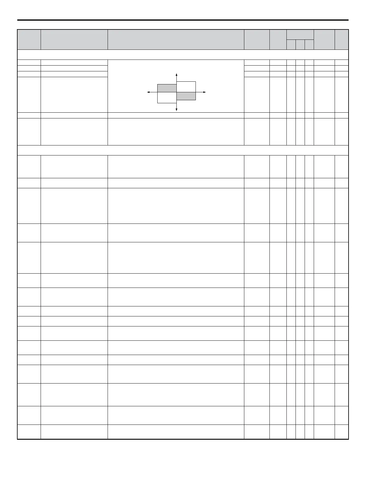
L7-01 Forward Torque Limit Sets the torque limit value as a percentage of the motor rated torque. Four
individual quadrants can be set.
L7-01
L7-03
L7-02
L7-04
output torque
positive torque
REV
negative torque
FWD
motor
r/min
regeneration
regeneration
0 to 300 200% − A − 4A7 —
L7-02 Reverse Torque Limit 0 to 300 200% − A − 4A8 —
L7-03 Forward Regenerative Torque Limit 0 to 300 200% − A − 4A9 —
L7-04 Reverse Regenerative Torque Limit 0 to 300 200% − A − 4AA —
L7-06 Torque Limit Integral Time Constant Sets the integral time constant for the torque limit. 5 to 10000 200 ms − A − 4AC —
L7-07
Torque Limit Control Method
Selection during Accel/Decel
Selects the method of torque limit control during accel/decel.
0: Proportional Control (change to integral controls at fixed speeds). Use this
setting when acceleration to the desired speed has priority over torque limitation.
1: Integral Control. Use this setting if the torque limitation has priority.
When torque limit is applied to the motor, accel/decel time may increase and
motor speed may not meet the speed reference.
0, 1 0 − A − 4C9 —
L8: Hardware Protection
Use L8 parameters to configure hardware protection functions.
L8-01
Internal Dynamic Braking Resistor
Protection Selection (ERF type)
Selects the Braking resistor when using a 3% duty cycle heatsink mounted
Yaskawa braking resistor. This parameter does not enable or disable the braking
transistor of the drive.
0: Resistor overheat protection disabled
1: Resistor overheat protection enabled
0, 1 0 A A A 4AD —
L8-02 Overheat Alarm Level
When the heatsink temperature exceeds the value set in this parameter, an
Overheat Alarm (OH) will occur.
50 to 130 <12> A A A 4AE —
L8-03
Overheat Pre-Alarm Operation
Selection
Sets the drive operation when an overheat alarm OH is detected.
0: Ramp to Stop using the active decel time.
1: Coast to Stop.
2: Fast-stop using the time set in C1-09.
3: Alarm Only. Drive continues running, but displays an alarm.
4: Reduced Speed Operation. Drive continues to run with reduced frequency
reference as specified in L8-19.
Settings 0 through 2 trigger a fault relay if the heatsink becomes too hot.
0 to 4 3 A A A 4AF —
L8-05 Input Phase Loss Protection Selection
Selects the detection of input current phase loss, power supply voltage imbalance,
or main circuit electrolytic capacitor deterioration.
0: Disabled
1: Enabled
0, 1 1 <56> A A A 4B1 —
L8-07 Output Phase Loss Protection
Selects the output phase loss detection.
0: Disabled
1: Enabled (triggered by a single phase loss).
2: Enabled (triggered when two phases are lost).
Output phase loss is detected when operating with less than 5% of the drive rated
current. Detection can mistakenly occur if the motor is too small relative to the
drive capacity rating (this parameter should be disabled in such cases).
0 to 2 0 A A A 4B3 —
L8-09
Output Ground Fault Detection
Selection
Selects the output ground fault detection.
0: Disabled
1: Enabled
0, 1 <12> A A A 4B5 —
L8-10
Heatsink Cooling Fan Operation
Selection
Controls the heatsink cooling fan operation.
0: Fan On-Run Mode - Fan will operate only when the drive is running and for
L8-11 seconds after stop.
1: Fan always on - Cooling fan operates whenever the drive is powered up.
0, 1 0 A A A 4B6 —
L8-11
Heatsink Cooling Fan Operation Delay
Time
This parameter sets the delay time for the cooling fan to shut off after the run
command is removed when L8-10 = 0.
0 to 300 60 s A A A 4B7 —
L8-12 Ambient Temperature Setting
Used to input the ambient temperature. This value adjusts the drives OL2
detection level.
-10 to 50 40 °C A A A 4B8 —
L8-15
OL2 Characteristics Selection at Low
Speeds
Sets the OL2 characteristics at output frequencies below 6 Hz.
0: No OL2 level reduction below 6Hz.
1: OL2 level is reduced linearly below 6 Hz. It is halved at 0 Hz.
0, 1 1 A A A 4BB —
L8-18 Soft CLA Selection
Selects the software current limit function. Typically no adjustment is required.
0: Disabled
1: Enabled
0, 1 1 A A − 4BE —
L8-19
Frequency Reduction Rate during OH
Pre-Alarm
Specifies the frequency reference reduction gain at overheat prealarm when
L8-03 = 4.
0.1 to 1.0 0.8 A A A 4BF —
L8-29 Current Unbalance Detection (LF2)
Selects the detection of unbalanced output currents caused by faulty devices in
the output circuit.
0: Disabled
1: Enabled
0 to 1 1 − − A 4DF —
L8-35 Installation Method
Selects the installation type:
0: Standard installation of Open Chassis drive
1: Side-by-Side installation with top cover removed
2: Standard Installation of NEMA Type 1 drive
3: Finless / Fin outside installation
0 to 2
<12>
<25>
Α Α A 4ECH —
L8-38 Carrier Frequency Reduction
Provides protection to the IGBTs by reducing the carrier frequency at low speeds.
0: Disabled
1: Enabled below 6 Hz
2: Enabled for the whole speed range
0 to 2 0 A A A 4EF —
L8-40 Carrier Frequency Reduction Time
Sets the time for that the drive continues running with reduced carrier frequency
after the carrier reduction condition has gone (see also L8-38).
A setting of 0.00 s disables the carrier frequency reduction time.
0.00 to 2.00 0.50 A A A 4F1
B.2 Parameter Table
314
YASKAWA ELECTRIC SIEP C710606 18A YASKAWA AC Drive – V1000 Technical Manual (Preliminary)

 Loading...


