Introduction LED Behavior
Software Reference for SwitchBlade x3100 Series Switches (Setting Up the Switch)
1-186
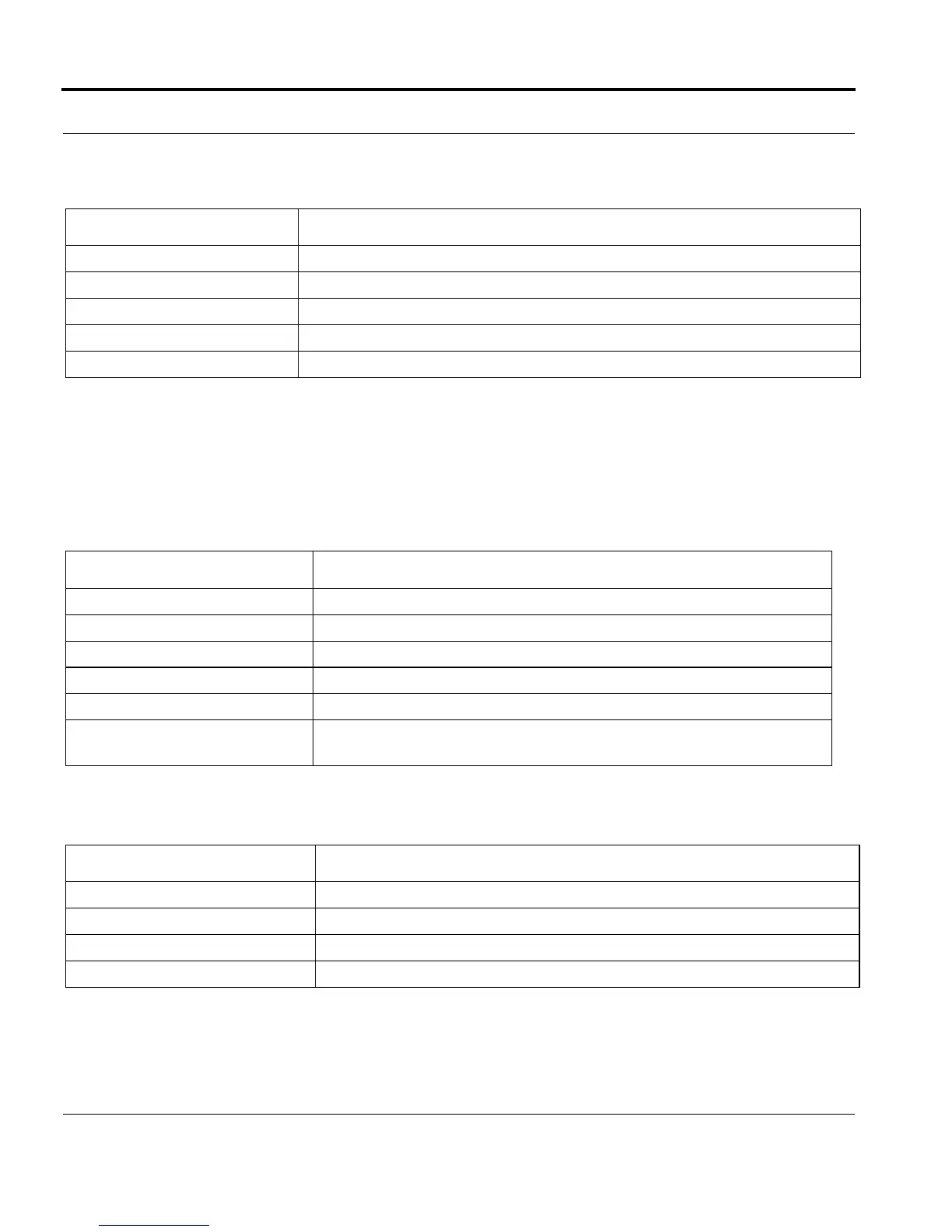
The following table illustrates the display of the MGMT interface LEDs over various states.
Disabling of the physical Ethernet layer for the MGMT interface is not supported; however, disable/enable of
the IP service on the interface will affect whether or not the interface is actively passing data (flashing LED).
This is the same behavior as other iMAP products.
The following table illustrates the display of the port activity LEDs on the GE24POE/GE24SFP over various
states:
The following table illustrates the display of the port LEDs on the XE4 over various states:
TABLE 1-37 MGMT Interface State and LED State
MGMT Interface State L/A LED State (on Corresponding CFC200
UP-UP-Online (1000 LINK) Solid Green
UP-UP-Online (1000 ACT) Flashing Green
UP-UP-Online (10/100 LINK) Solid Amber
UP-UP-Online (10/100 ACT) Flashing Amber
UP-DN-Failed Off
TABLE 1-38 GE Interface State and Port Activity LED State on GE Cards
GE Interface State Port Activity LED State (on Corresponding GE24POE/GE24SFP
UP-UP-Online (1000 LINK) Solid Green
UP-UP-Online (1000 ACT) Flashing Green
UP-UP-Online (10/100 LINK) Solid Amber
UP-UP-Online (10/100 ACT) Flashing Amber
UP-DN-Offline Off
UP-DN-Failed Off (Note that since the LED shows link-state, there could be a BFD failure,
where the port may be operationally down but the LED could still be On.
TABLE 1-39 XE Interface State and Port Activity LED State on XE4
XE Interface State Port Activity LED State (on Corresponding XE4
UP-UP-Online (10000 LINK) Solid Green
UP-UP-Online (10000 ACT) Flashing Green
DN-DN-Offline Off
UP-DN-Failed Off

 Loading...


