Introduction Configuring LAG
Software Reference for SwitchBlade x3100 Series Switches (Layer Two Switching)
4-36
CREATE LAG
Syntax
CREATE LAG=lagname
[ INTERFACE={ type:id-range | id-range | ifname-list } ]
[ MODE={ ON | OFF | PASSIVE | ACTIVE } ]
[ ADMINKEY=1..1024 ]
Description Creates a Link Aggregation Group (LAG). When a LAG is created, the user must specify
a unique identifier or allow the system to assign an identifier. The LAG ID is used for SET,
DESTROY, SHOW, ADD, and DELETE commands for the LAG. Optionally, ports belong-
ing to the LAG can be specified at LAG creation time, as well as the MODE, SELECT cri-
teria, and ADMINKEY. Interfaces can also be added to the LAG at a later time via ADD
LAG command. The MODE, SELECT, and ADMINKEY parameters can all be set at a
later time, using the SET LAG command.
Options The following table gives the range of values for each option that can be specified with
this command and a default value (if applicable).
Example CREATE LAG=card1_card8 INTERFACE=1.0,1.1
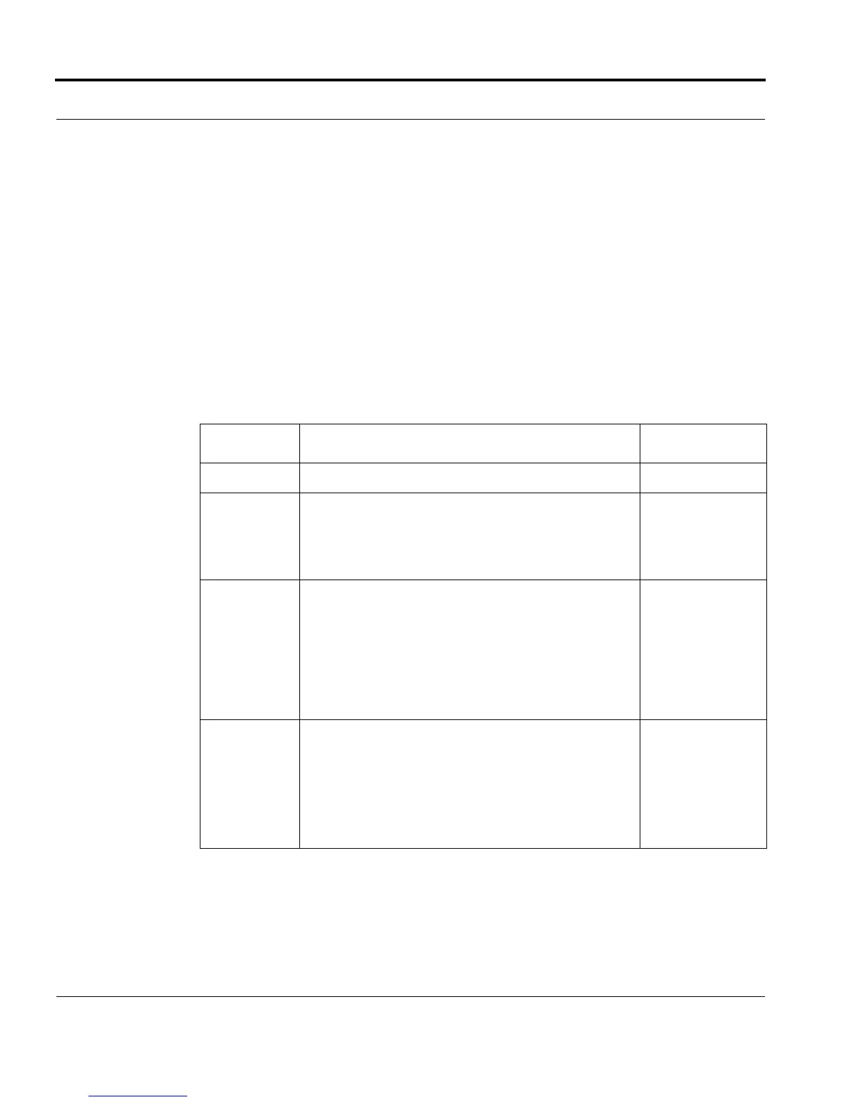
Option Description Default Value
LAG The lagname to be created. N/A
INTERFACE The XE or GE interfaces that will be included in the
LAG. These can be added
individually or as a comma-
separated id-ranges or as a forward-slash sepa-
rated type:id-ranges.
N/A
MODE OFF - disables aggregation for the specified interfaces in
the LAG.
ON - enables aggregation for the specified interfaces in
the LAG. For aggregation to work, the interfaces in the
LAG must be connected to interfaces in a LAG on the
other end, that is also in the ON mode. This is “stati-
cally configured link aggregation.”
OFF
ADMINKEY The 802.3ad admin key value for the LAG. It is used to
identify specific groups of ports capable of aggregation.
A default value is set by the system if one is not speci-
fied.
Range is 1..1024
N o t e t h a t h i g h e r v a l u e s r e p r e s e n t l o w e r p r i o r i t y .
Automatically
assigned, default
value of 1.
 Loading...


