Introduction SuperLoop Prevention
Software Reference for SwitchBlade x3100 Series Switches (Layer Two Switching)
4-132
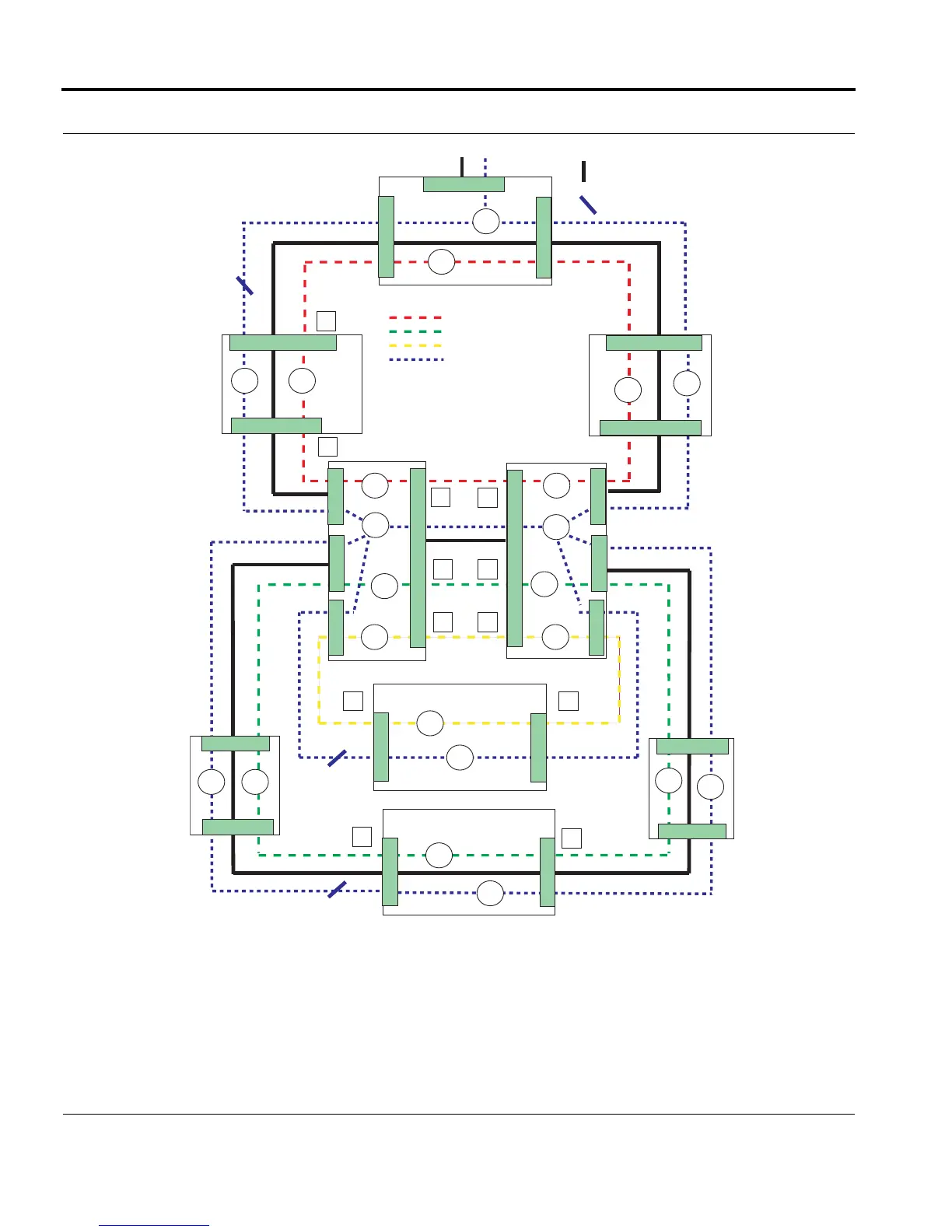
FIGURE 4-13 Ring Interface Priorities - Ring Segments
V_60
V_80
V_80
127
127
127
127
126126
126
126
V_60
V_60 V_60
V_80
V_80
V_80
V_80
V_60
0.3
= Data VLAN (V_80)
= Ring 1 Control VLAN (V_60)
= Ring 2 Control VLAN (V_90)
= Ring 3 Control VLAN (V_40)
0.1
0.2
0.2
0.3
0.2
0.1
0.2
0.1
Master
Node
(M2)
Master
Node
(M1)
To / From Network
V_80
V_90
0.2
0.1
V_80 V_90
V_90
V_40
V_40
V_90
0.2
V_80
V_90
SP
SP
PP
PP
0.1
0.1
0.2
0.3
0.1
0.1
Note 1
125125
Note 1 Note 1
125
Master Node
(M3)
V_40
Note 1
125
Note 1
Note 1
Note 2
Note 2
= Interface priorities of Master Node
and common link interface match
= Physical Link
EPSR_Topology_SuperLoop_nested
= EPSR Blocking
Note 2
= Interface priorities of Transit Nodes
not including common link are 0
(default value)
1.0
1.1
0.1
0.2
0.2
0.2

 Loading...


