Protected by copyright. Copying for private or commercial purposes, in part or in whole, is not
permitted unless authorised by AUDI AG. AUDI AG does not guarantee or accept any liability
with respect to the correctness of information in this document. Copyright by AUDI AG.
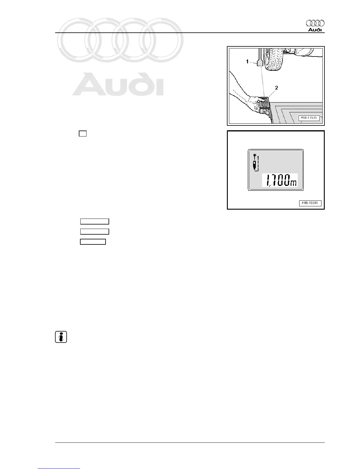
– To measure distance, hold spacing laser -VAS 6350/2-
-item 2- flush with locating bracket as shown in illustration.
• Spacing laser -VAS 6350/2- must be steady and flush with lo‐
cating bracket.
– Make sure that laser beam for distance measurement hits
lower (larger) part of measuring paddle -1-.
If this is not the case, adjust height of measuring paddles using
lock nuts on wheel centre mountings - VAS 6350/1- .
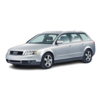
– Press ON button briefly to measure distance.
Display on -VAS 6350/2- :
• “1.700 m” (specification: 1,700 ± 2 mm).
– Repeat measurement from locating bracket (right-side) to rear
right wheel.
• Measured distance value must be identical on both sides.
If the two measured values are not identical, re-align calibration
unit - VAS 6350- .
Performing calibration
⇒ Vehicle diagnostic tester is connected.
– Select Diagnosis mode and start diagnosis.
– Select Test plan tab.
– Select Own test then the following options one after the oth‐
er:
♦ Body
♦ Electrical system
♦ 01 - Self-diagnosis compatible systems
♦ 3C - Lane change assist control unit - J769
♦ 3C - Lane change assist control unit, functions
♦ 3C - Calibration
Further instructions are given by ⇒ Vehicle diagnostic tester dur‐
ing calibration procedure.
Note
♦
The system will now inform you which lane change assist ver‐
sion is fitted in the vehicle (e.g. version 1.0).
♦
This information for setting the calibration unit is important for
the work sequence to be followed and to avoid malfunctions.
Audi A8 2003 ➤
Electrical system - Edition 08.2014
12. Lane change assist 325