State transition 3 (command “Switch on” [0x07]) is only processed if bit no. 4 “Volt-
age enabled” of the Status word is set.
State transition 4 (command “Enable operation” [0x0F]) is only processed if the re-
lease is set via hardware contacts STO.
If the hardware release via STO is not set, the frequency
inverter remains in state
“Switched On” [0x33] until the hardware release is set via STO.
If in state “Operation enable” [0x37] the STO hardware release is reset, the state is
switched internally into state “Switched On” [0x33].
In configurations with motion control (p.30 = x40) consider the following points:
• State transition 4’ is not available.
• In status “5 –
Operation enabled 0x37” an additional start signale has to be
set via the “High-
Byte” of the control word to start a motion of the motor.
The start signal of this Motion Control Interface (MCI) is described in cha
ter 14.4. To change into another MCI operation mode Object 0x6060
of Operation can be used.
•
The controller release (STOA and STOB) must be set. Start clockwise and
start anticlockwise have no function in motion control configurations.
In configurations without motion control (p.30 ≠ x40) consider the following points:
• State transition 4’ is available and is only processed if bit no. 4 “Voltage en
bled” of the Status word
is set. This function is for downward compatibility to
older software versions.
•
The inverter can only be controlled via the state machine if the logic linking is
true. The logic inputs for Start clockwise / Start anticlockwise can be connec
ed directly to ON/OFF (p.68, p.69).
The controller release (STOA and STOB) must be set.
Therefore this results in:
Release: ( = STOA AND STOB) AND (Start clockwise OR Start anticlockwise)
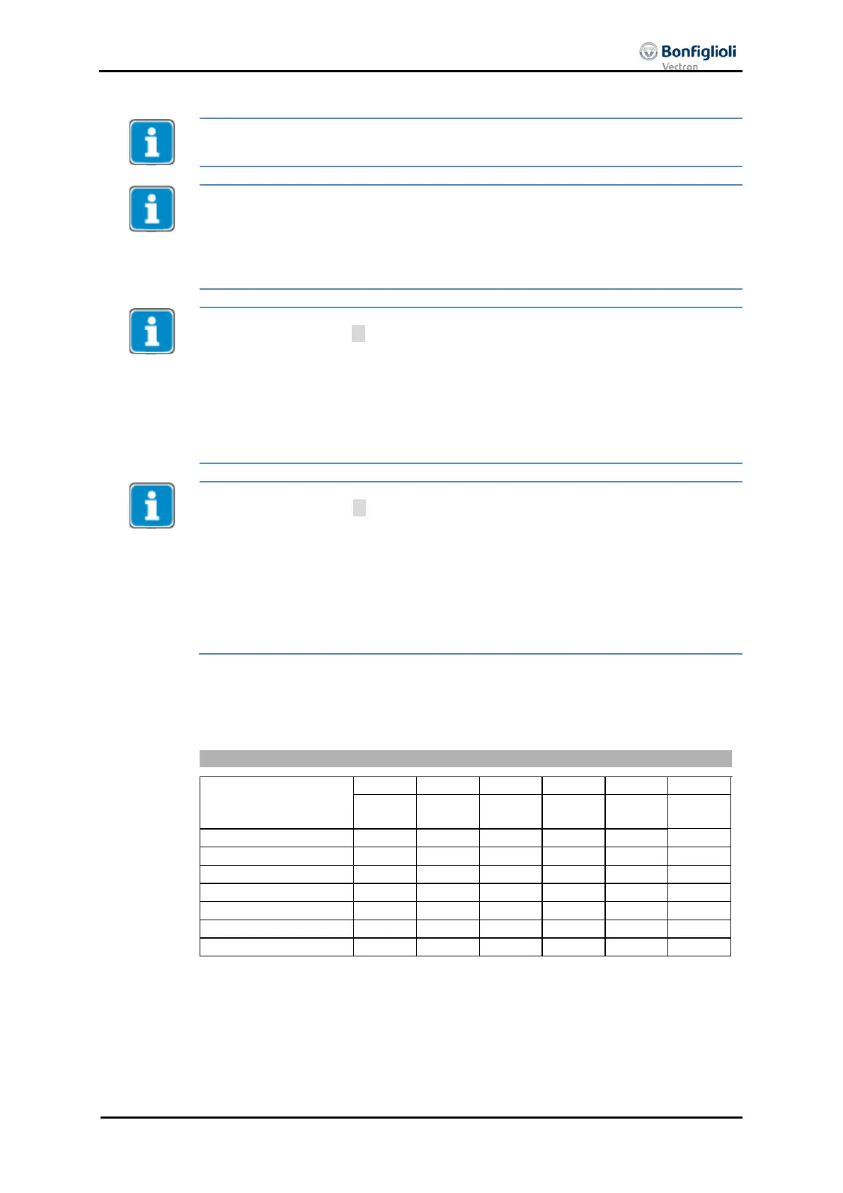
The
Status word
displays the current operation state.
disabled
stop
enabled
on
switch on
Bits marked X are irrelevant
Bit 7, Warning, can be set at any time. It indicates a device-internal warning mes-
sage. The evaluation of the warning reason is carried out by reading out the warning
status with the parameter Warnings 270.
Bit 9, Remote, is set if the operation mode "control via state machine" (Lo-
cal/Remote
412 = 1) has been set and the hardware release is available.
04/13 CM-CAN ACU 171

 Loading...


