Alternatively the parameters 1123, 1124 and 1142 can be used instead of the Objects.
Usage of the Objects will write the parameters in RAM (data set 5).
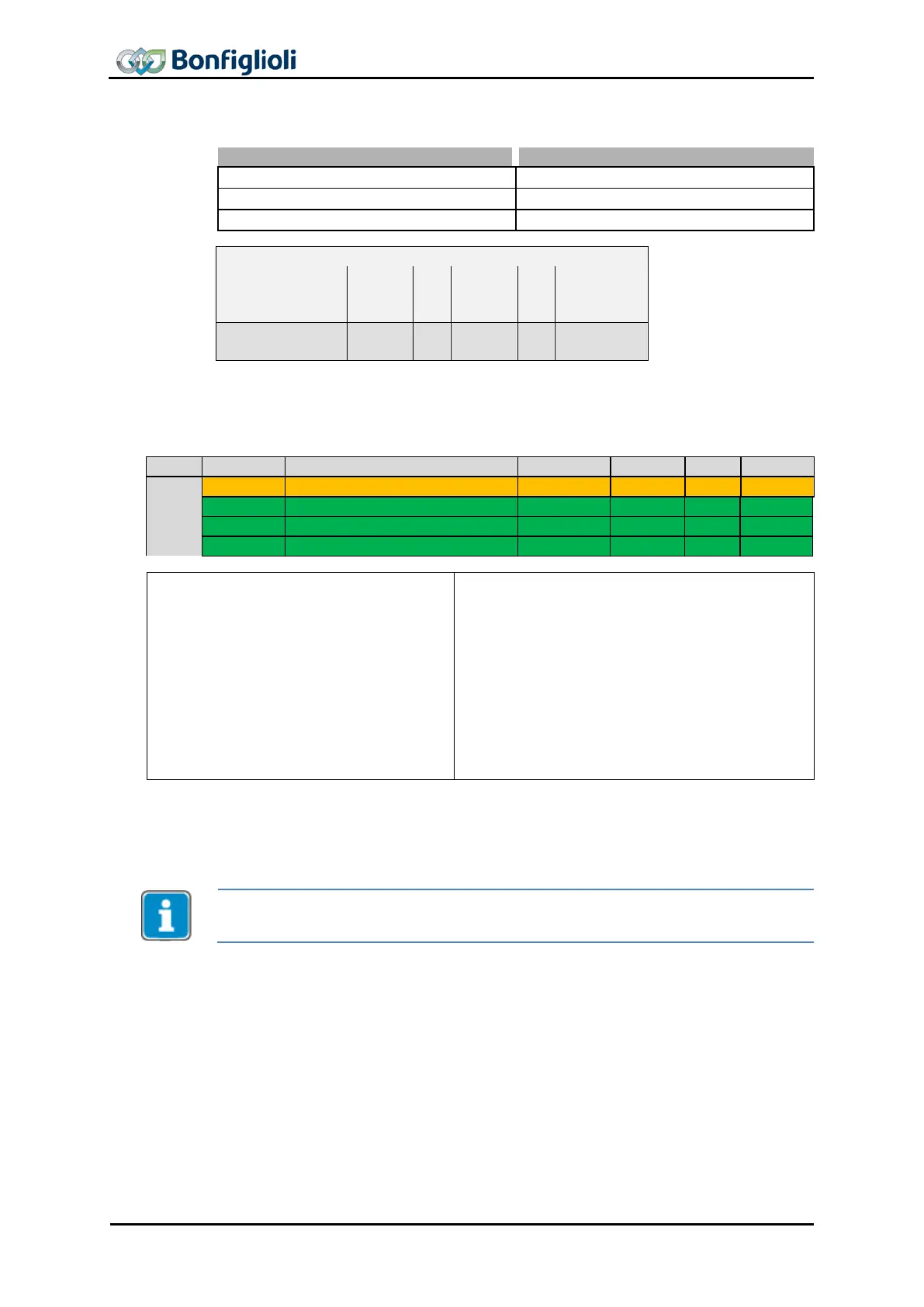
Gear factor Resync on change
Resync. on Change of Gear-Factor
CB: Control byte SI: Sub Index All values in hexadecimal without leading 0x
12.4.19 0x5F11/n…0x5F14/n Phasing 1…4
Highest sub-index supported
• Motion Control:
o Electronic Gear: Slave
o
mode
(Electronic Gear operation)
• Motion Control:
o Profile Positioning mode
o Velocity mode
o Profile Velocity mode
o Homing mode
o Interpolated mode
o Table Travel Record mode
o Move away from Limit Switch
• Non motion Control (conf. ≠ x40)
Objects 0x5F11
Phasing 1
, 0x5F12
Phasing 2,
0x5F13
Phasing 3
and
0x5F14
Phas-
ing 4
active motion block
is available in
Electronic Gear: Slave
configurations (P.30 = x40). The
table travel record
mode is activated by object
0x6060
modes of operation
set to -3.
For better readability in the following section Object 0x5F11 is used. For Objects
0x5F12, 0x5F13 und 0x5F14 the descriptions apply analogously.
With the phasing function, the slave position is offset from the received position of the
master by the value entered in 0x5F11/1
Phasing 1: Offset
.
The function can is started via Bit 9 of the Control Word. After start, 0x5F11/2
Pha
ing 1: Speed
and 0x5F11/3
Phasing 1: Acceleration
are used until the slave position is
offset from the master position by
Phasing 1: Offset
.
During Phasing the Status word bit 8 “Phasing Done” is set to “Low”. As soon as the
Phasing is finished or cancelled, the Bit is set to “High”. After first switch-
on (or after
a device reset) the “Phasing Done” bit is also “Low”.
102 CM-CAN ACU 04/13

 Loading...


