6 Connector pin assignment/bus termination/line
The CAN connection is physically designed according to the ISO 11898 standards
(CAN High-Speed).
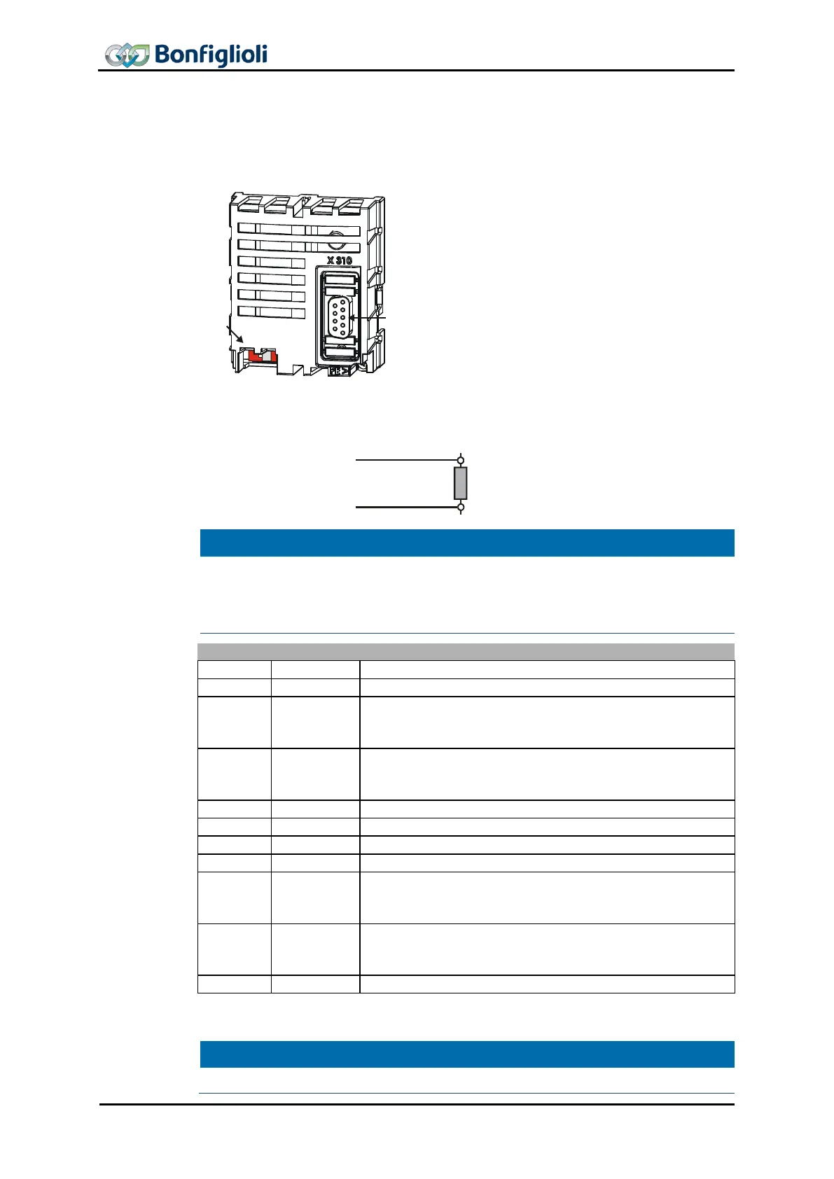
The X310 (9-pole Sub-D) bus plug has been
designed according to DS102 Version 2.0 (Bus
node, option A).
Details can be seen from the following table on
the occupancy of the bus plug.
The bus termination necessary on a phase in the
physically first and last subscriber can be act
vated via DIP switch S1
module.
The factory setting for the bus termination is OFF.
As an alternative, this is also possible via corresponding switching in the bus connec-
tion plugs.
CAN high (Pin 7)
120 Ω
CAN low (Pin 2)
data line
data line
NOTE
Make absolutely sure that only one of the two possibilities for the bus termination is
used and the bus termination is only switched on with the
first and last subscriber.
Otherwise, operation of the CANopen
®
communication is not possible. The CAN
Controller State is displayed via actual value parameter CAN-State 1291.
short-circuit resistant and function-insulated,
short-circuit resistant and function-insulated,
short-circuit resistant and function-insulated,
short-circuit resistant and function-insulated,
The drilled and shielded line is to be used for the bus line. The shield is to be imple-
mented as a harness shield (not a film shield).
NOTE
Connect the line screen with PE at both ends.
26 CM-CAN ACU 04/13