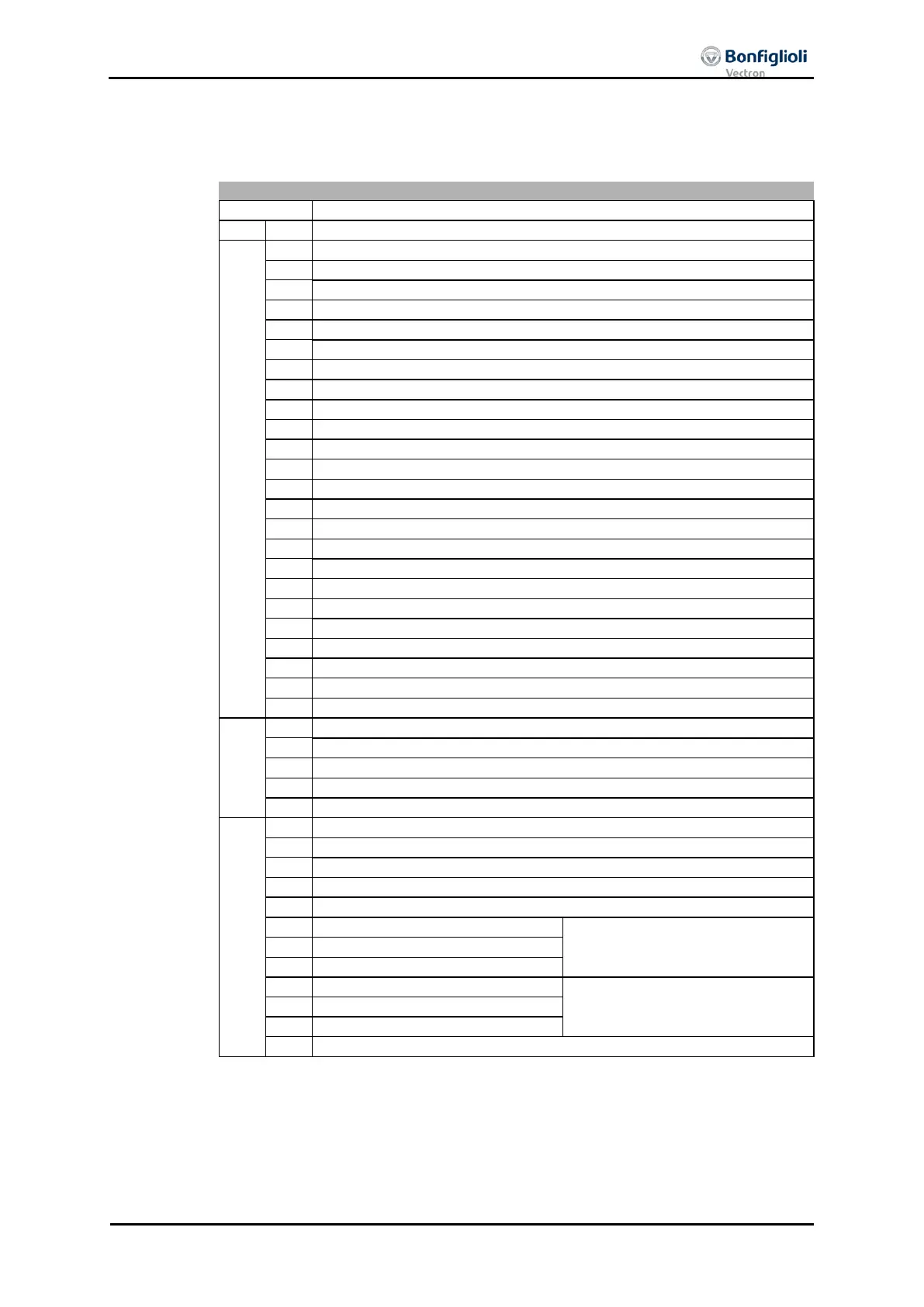
16.5 Fault messages
The fault code that is stored after a fault occurs is made up of the fault group FXX
(high Byte, hexadecimal) followed by the code number XX (low Byte, hexadecimal).
Control Deviation Position Controller
Pos. SW-Lim. Switch < Neg. SW-Lim. Switch
Pos. and Neg. HW-Lim Switch Simultaneously
Limit Switch Incorrect Wired!
Clockwise Operation Locked
Anti-Clockwise Operation Locked
System bus-Synchronization not activated
Pos. HW-Lim. Switch: Illegal Signal Source
Pos. HW-Lim. Switch: Input disabled by PWM-/FF-Input
Pos. HW-Lim. Switch: Input disabled by Index-Contr.
Pos. HW-Lim. Switch: Wrong Op.-Mode for MFI1
Pos. HW-Lim. Switch: Input disabled by Encoder 1
Pos. HW-Lim. Switch: Input disabled by Encoder 2
Pos. HW-Lim. Switch: Wrong Op.-Mode for EM-S1IOD
Neg. HW-Lim. Switch: Illegal Signal Source
Neg. HW-Lim. Switch: Input disabled by PWM-/FF-Input
Neg. HW-Lim. Switch: Input disabled by Index-Contr.
Neg. HW-Lim. Switch: Wrong Op.-Mode for MFI1
Neg. HW-Lim. Switch: Input disabled by Encoder 1
Neg. HW-Lim. Switch: Input disabled by Encoder 2
Neg. HW-Lim. Switch: Wrong Op.-Mode for EM-S1IOD
User-Defined Error in Motion Block xx (1 £ xx £ 32)
Homing : Encoder-Mode w.o. Z-Impulse
No Touch Probe Signal Detected
NMT state change (operational xxx)
(number of received bytes different
to mapping)
(The RxPDO was not received in
the set time. Check object
0x140n/5 Event time.)
Heartbeat failure – nn = node address of the failed subscriber (hex)
The Actual error message can be read out by parameter access via parameter Actual
Error
260 and via the Emergency Message or Object 0x1014.
Parameter Actual Error 259 shows the actual error in clear text on the operator pa
el and the PC software tool VPlus.
In addition to the fault messages stated, there are further fault messages described in
the Operating Instructions. The faults o
f the Motion Control Interface (F14xx, F15xx)
are described detailed in the application manual “Positioning”.
04/13 CM-CAN ACU 231