EasyManua.ls Logo

BONFIGLIOLI Vectron Active Cube User Manual

BONFIGLIOLI Vectron Active Cube
240 pages
To Next Page IconTo Next Page
To Previous Page IconTo Previous Page
Page #128 background image
12.5.17 0x6067/0 Position window
Index
Sub-index
Meaning
Data type
Access
Map
Def.-Val
0x6067
0
Position window
Unsigned32
rw
No
0xFFFF FFFF
Object works in:
Motion Control:
o All modes
Object doesn’t work in:
Non motion Control (conf. x40)
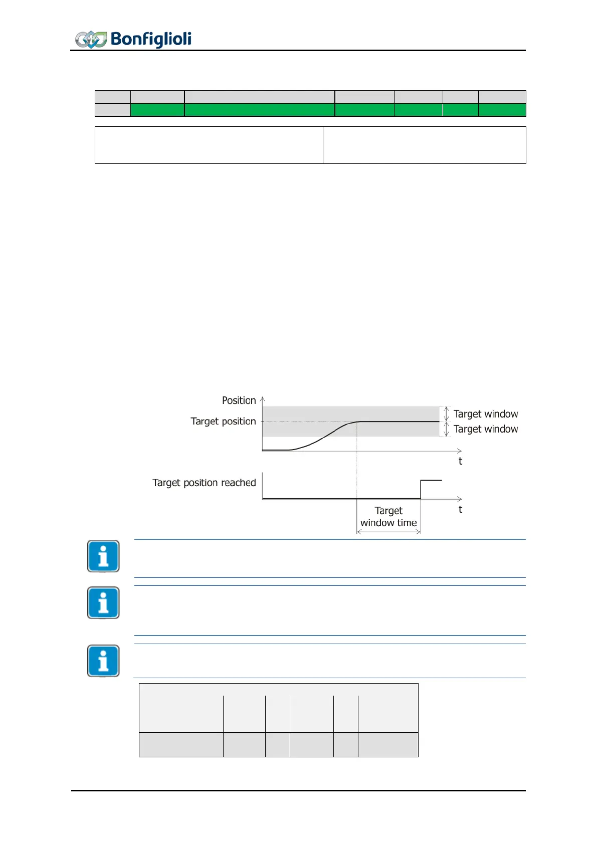
The signal “target position reached” can be changed in accuracy with Object 0x6067
position window
for the modes which use Status Word Bit 10 “Target reached” as
“Target Position reached” like “Profile Positioning Mode” and “Table Travel Record
Mode”.
Object 0x6067
position window
defines a symmetrical range of accepted positions
relative to the target position in user units. If the actual value of the position mea
s-
urement device is within the position window, the target position is regarded as
reached. “Target reached” is displayed in Bit 10 of the status word. The actual pos
i-
tion must be inside the position window during the time specified in Object
0x6068
position window time
.
If the actual position drifts outside the target window or if a new target position is set,
the “Target reached” Bit is reset until the position and time conditions are met again.
The valid value range of object 0x6067/0
position window
is 0 … 0x7FFF FFFF (2
31
-
1).
Writing a value of 0x8000 0000 (2
31
)0xFFFF FFFE (2
32
-
2) results in an SDO abort
(value range).
If the value of
position window
is set to 0xFFFF FFFF (2
32
-1) OR 0, the position wi
n-
dow control is switched off.
Writing to object
position window
automatically generates a write command to parame-
ter Target Window 1165 (data set 5, all data sets in RAM only !).
If object 0x6067/0 was written and then a save parameters command (object 0x1010)
processed, the object value is stored in non volatile memory.
After the next power on of the inverter, the previously set value is reactivated and
overwrites the setting of Target Window 1165.
The dimension of the user units is defined by 0x6091
Gear ratio
and 0x6092
Feed con-
stant
.
Example:
COB ID
CB
Index
SI
Data
Read Request
601
40
67 60
00
00 00 00 00
Reply
581
43
67 60
00
FF FF FF FF
Write Access
601
23
67 60
00
10 27 00 00
Reply
581
60
67 60
00
00 00 00 00
CB: Control byte SI: Sub Index All values in hexadecimal without leading 0x
128 CM-CAN ACU 04/13

Table of Contents

Question and Answer IconNeed help?

Do you have a question about the BONFIGLIOLI Vectron Active Cube and is the answer not in the manual?

BONFIGLIOLI Vectron Active Cube Specifications

General IconGeneral
BrandBONFIGLIOLI
ModelVectron Active Cube
CategoryDC Drives
LanguageEnglish

Summary

1 General Information about the Documentation

Quick Start Guide

Provides basic steps for mechanical and electrical installation of the frequency inverter.

User manual

Details the complete functionality of the frequency inverter and parameters for special purposes.

Application manual

Complements installation and commissioning guidance for the frequency inverter.

1.2 Warranty and liability

1.3 User Obligation

1.4 Copyright and Usage Restrictions

1.5 Documentation Storage

2 General safety instructions and information on use

2.1 Terminology

Defines terms for different groups of persons involved in operating the frequency inverter.

2.2 Designated use

Describes the intended purpose and compliance requirements for the frequency inverter.

2.3 Misuse and Explosion Protection

Details impermissible uses, manufacturer liability, and device's IP20 rating for explosive atmospheres.

2.4 Residual risks

Identifies hazards that cannot be eliminated despite safety-compliant design, such as electrical, thermal, and mechanical risks.

2.5 Safety and warning signs at frequency inverter

Emphasizes compliance with safety instructions and not removing warning signs on the inverter.

2.6 Warning information and symbols

Explains hazard classes, symbols, prohibition signs, and safety equipment for user manual guidance.

2.6.1 Hazard classes

Defines hazard classes like DANGER, WARNING, CAUTION, NOTE for risk identification.

2.6.2 Hazard symbols

Illustrates common hazard symbols such as General hazard, Electrical voltage, Hot surfaces.

2.6.3 Prohibition signs

Displays prohibition signs, e.g., 'No switching; it is forbidden to switch the machine/plant'.

2.6.4 Personal safety equipment

Shows a symbol for personal safety equipment, meaning 'Wear body protection'.

2.6.6 Grounding, ESD, and Information Symbols

2.7 Directives and guidelines to be adhered to by the operator

2.8 Operator's general plant documentation

Operator should issue internal operating instructions and include the user manual in the plant manual.

2.9 Operator's/operating staff's responsibilities

Covers staff selection, qualification, and general work safety responsibilities.

2.9.1 Selection and qualification of staff

Specifies that only qualified technical staff, not under influence of drugs, may work on the inverter.

2.9.2 General work safety

Emphasizes compliance with accident prevention, environmental regulations, and use of PPE.

2.10 Organizational measures

2.10.1 General

Includes staff training, prohibition of component reuse, and use of optional components as per documentation.

2.10.2 Use in combination with third-party products

States manufacturer's non-responsibility for compatibility with third-party products.

2.10.3 Transport and Storage

Specifies requirements for transport and storage, including dry rooms and temperature deviations.

2.10.4 Handling and installation

Details precautions for handling, avoiding mechanical overloading, and proper installation environment.

2.10.5 Electrical connections

Requires compliance with safety rules, avoiding live terminals, and connecting to suitable supply mains.

2.10.5.1 The five safety rules

Lists the five critical safety rules for working on electrical plants: Isolate, Secure, Check, Earth, Cover.

2.10.6 Safe operation

Provides guidelines for safe operation, including compliance with regulations, checking covers, and waiting after shutdown.

2.10.7 Maintenance and service/troubleshooting

Covers visual inspection, proper maintenance execution, and authorized repair personnel.

3 Introduction

3.1 Supported Configurations

Describes the different types of control and reference values supported by ACTIVE CUBE inverters.

4 First Commissioning

Installation of the Module

Details the steps for installing the CM-CAN communication module.

Settings for CANopen Communication

Covers setting the baud rate, node address, and device control parameters.

Commissioning the device function via PLC

Explains how to commission the device function via PLC, including reaction to boot-up and PDO mapping.

5 Installation/Disassembly of the communication module

5.1 Installation

Provides step-by-step instructions for installing the CM-CAN communication module into the frequency inverter.

5.2 Disassembly

Details the procedure for safely disassembling the CM-CAN communication module from the frequency inverter.

6 Connector pin assignment/bus termination/line

7 Baud rate setting/line lengths

8 Setting the node number

9 Assigning the CANopen interface

10 Operational behavior on bus failure

11 CANopen Overview

11.1 Communication Objects

Describes communication objects located in index range 0x1nnn, including device information.

11.2 Application Objects

Divides application objects into manufacturer-specific (0x2nnn) and device profile-specific (0x6nnn).

11.3 SDO Function

Explains the use of Service Data Objects (SDO) for reading and writing objects in the object dictionary.

11.4 PDO Function

Describes Process Data Objects (PDO) for transmitting process data, including mapping and default identifiers.

11.5 Emergency Function

Explains the emergency message sent by the inverter in case of communication or internal errors.

11.7 NMT Functions

Covers Network Management (NMT) functions, state machine, and error control.

11.8 Guarding

Describes the Guarding response, activation, fault behavior, and sequence for PLC monitoring.

11.9 Heartbeat

Explains the heartbeat mechanism for producer/consumer monitoring and NMT state reporting.

11.10 OS Synchronization

Details OS synchronization via CANopen or Systembus for enhancing plant performance.

11.11 Fault Reset

Describes how to perform a fault reset depending on control settings and operating status.

12 Objects

12.1 Objects tabular overview

Presents a table defining access types, data types, and PDO mapping for available objects.

12.2 Communication Objects (0x1nnn)

Details communication objects (0x1nnn) containing parameters for communication.

12.3 Manufacturer objects (0x2nnn) – Parameter access

Explains parameter access via SDO channel using index and sub-index.

12.4 Manufacturer objects (0x3000 … 0x5FFF)

Lists manufacturer-specific objects for various functions like SYNC Jitter, digital I/O, and percentage values.

12.5 Device Profile Objects (0x6nnn)

Lists device profile specific objects (0x6nnn) defined by DS402 for motion control functions.

12.5.1 0x6007/0 Abort Connection option code

Specifies the inverter's operational behavior upon bus connection failure.

12.5.3 0x6040/0 Control word

Relevant to the inverter remote state machine; controls operations like Switch on, Enable voltage, Halt.

12.5.4 0x6041/0 Status word

Displays the actual state of the inverter, indicating Ready to switch on, Switched on, Operation enabled, Fault, etc.

12.5.5 0x6042/0 Target velocity [rpm]

Sets the speed reference value for the frequency inverter in RPM.

12.5.12 0x6060/0 Modes of operation

Sets the designated operation mode of the inverter, e.g., Velocity, Homing, Interpolated.

12.5.15 0x6065/0 Following error window

Sets the threshold for a device warning when the following error becomes too large.

12.5.28 0x607A/0 Target position

Defines the target position in user units for movement in profile position mode.

12.5.30 0x6081/0 Profile velocity [u/s]

Sets the velocity at the end of the acceleration ramp in profile position mode.

12.5.37 0x6098/0 Homing method

Determines the method used during homing, such as using limit switches or home switches.

13 Motion Control Interface (MCI)

13.1 Object and parameter dependencies

Details dependencies between objects and parameters for different operational modes like Homing, Velocity, Profile Velocity.

13.3 Homing

Describes the homing operation to determine the reference point for positioning modes.

13.4 Position Controller

Evaluates positioning operations and controls drive for accuracy, with details on object 0x5F17.

13.5 Move away from Hardware limit switches

Describes how the drive moves away from activated hardware limit switches after a fault reset.

13.6 Motion Control Interface for Experts

Allows experienced users to change sources from CANopen to Systembus for Motion Control.

14 Inverter Control

14.1 Control via digital inputs/remote digital inputs

Explains control via digital inputs or remote inputs, and the use of Control word bits for emulation.

14.2 Control via state machine

Details control via state machine using the Control word, including state transitions and bit definitions.

14.3 Non motion control configurations

Configures the inverter for non-motion control, fixing modes of operation to velocity mode.

14.4 Motion control configurations

Describes motion control configurations, detailing specific modes like Velocity, Profile Velocity, and Homing.

14.4.1 Velocity mode [rpm]

Selects velocity mode via object 0x6060, controlling ramp function generator with Control word bits.

14.4.2 Profile Velocity mode [u/s]

Selects profile velocity mode via object 0x6060, receiving reference speed in user units [u/s].

14.4.3 Profile position mode

Selects profile position mode via object 0x6060, receiving target position followed by move command.

14.4.4 Interpolated position mode

Selects interpolated position mode via object 0x6060, receiving target position at equidistant time intervals.

14.4.5 Homing mode

Selects homing mode via object 0x6060 to move drive to a reference position using object 0x6098.

14.4.6 Table travel record

Selects table travel record mode via object 0x6060, moving drive autonomously to predefined positions.

14.4.7 Move away from Limit switches

Selects move away from limit switches mode via object 0x6060 to move drive back into travel area.

14.4.8 Electronic Gear: Slave

Selects electronic gear slave mode via object 0x6060, where drive follows master drive.

15 Parameter list

15.1 Actual values

Lists actual values of the frequency inverter, such as reference frequency, current error, and warnings.

15.2 Parameters

Lists configurable parameters for CAN bus, rated motor settings, bus control, and frequency ramps.

16 Annex

16.1 Control Word overview

Provides an overview of the functionality of the Control Word bits across different modes.

16.2 Status Word overview

Provides an overview of the functionality of the Status Word bits across different modes.

16.3 Warning messages

Lists warning messages activated by the communication module and their meanings.

16.5 Fault messages

Lists fault codes and their meanings for communication errors and CANopen-related issues.

17 Motion-control-interface for Profibus connection

Related product manuals