CDM-570/570L Satellite Modem with Optional IP Module Revision 12
Introduction MN/CDM570L.IOM
1–6
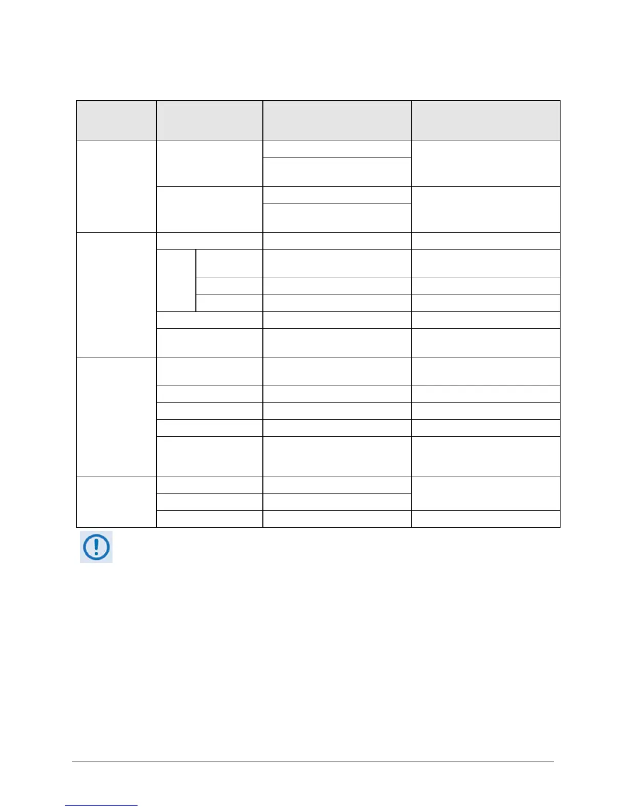
Table 1-1. Summary of CDM-570/570L Rear Panel Connectors
Connector Group
(Chapter 3
Sect. Ref.)
Name Connector Type Function
IF
(Sect. 3.2)
Rx
CDM-570L: Type ’N’ female (L-band)
IF Input
CDM-570: BNC female (70/140MHz
band)
Tx
CDM-570L: Type ’N’ female (L-band)
IF Output
CDM-570: BNC female (70/140MHz
band)
Terrestrial Data
(Sect. 3.3)
Data Interface 25-pin Type ‘D’ female Serial synchronous data Input/Output
G.703
Data
Balanced 15-pin Type ‘D’ female
G.703
T1 (1544 kbps) / E1 (2048 kbps)
Unbalanced Out
BNC 75Ω female Receive G.703 E1 (2048 kbps)
Unbalanced In BNC 75Ω female Transmit G.703 E1 (2048 kbps)
10/100 Ethernet M&C RJ-45 female 10/100 BaseT management and data
10/100 Ethernet Traffic RJ-45 female
(w/optional IP Module) Ethernet
Traffic
Utility
(Sect. 3.4)
Remote Control 9-pin Type ‘D’ male
Serial Remote Interface (EIA-232/-
485)
Alarms 15-pin Type ‘D’ male Form C Alarms (relay closures)
1:1 Control 9-pin Type ‘D’ female Connection to External 1:1 Controller
External Reference BNC female Input/Output
Serial Console RJ-11 female
(w/optional IP Module) EIA-232 Serial
Console for CDM-570L/IP Module
management
Power/Ground
(Sect 3.5)
AC See Sect. 3.5.1
Chassis power
DC (optional) See Sect. 3.5.2
Ground #10-32 stud Common Chassis Ground
The European EMC Directive (EN55022, EN50082-1) requires using properly shielded cables for DATA I/O.
These cables must be double-shielded from end-to-end, ensuring a continuous ground shield.
In addition to the connectors listed in Table 1-1, eig
ht LEDs are provided on the rear panel:
• Six of the LEDs, all orange, indicate the interface type currently selected: V.35, RS232,
RS422/EIA530, T1, E1-U, or E1-B.
• For systems in a redundant configuration, a green LED labeled “Online” indicates the
Online/Offline status of the unit.
• When the unit is connected to a 1:N switch, a red LED labeled “1:N CAUTION!”
indicates that caution is required, as there may be DC voltages and other control signals
present on certain pins on the 25-pin Data Interface connector.
Also associated with redundancy mode, a slide switch is provided that selects the 1:N mode.