CDM-570/570L Satellite Modem with Optional IP Module Revision 12
Appendix H MN/CDM570L.IOM
H–8
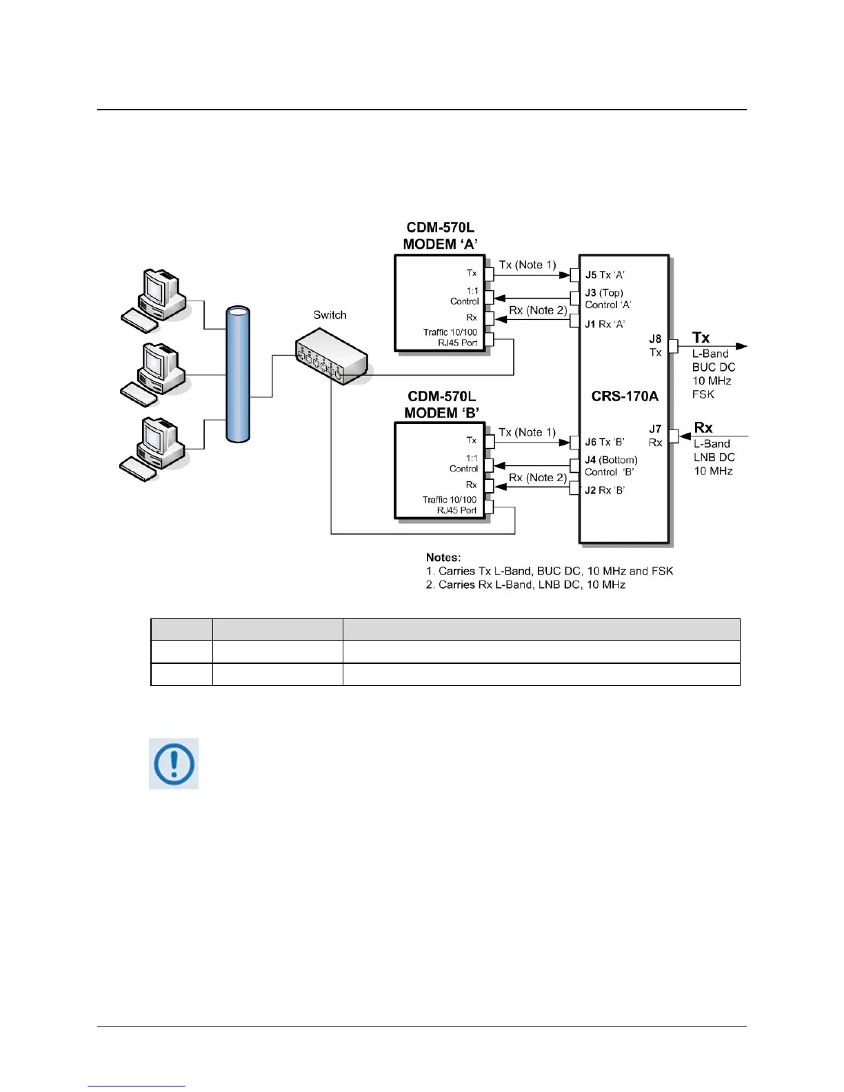
H.6 Cabling With CDM-570L
Figure H-4 shows how to connect a pair of CDM-570L modems together with the CRS-170A
L-Band 1:1 Redundancy Switch. The table that is included here lists cable assemblies that may be
supplied with the CRS-170A.
Quantity Part # Description
2 CA/WR9378-4 Control Cable, Universal, DB9 Male to Male, 4’
4 CA/RF10453-4 RoHS-Compliant Cable – IF (Tx/Rx), 50Ω Type ‘N’, 4’
Figure H-4. CDM-570L and CRS-170A Interconnect
When connecting the Control cable between the CRS-170A and the modems,
ensure that screw locks on the ‘D’ type connectors are securely fastened. This
will prevent the accidental unmating of the cable, particularly when a standby unit
is being removed or replaced.