CDM-570/570L Satellite Modem with Optional IP Module Revision 12
Rear Panel Connectors and Pinouts MN/CDM570L.IOM
3–2
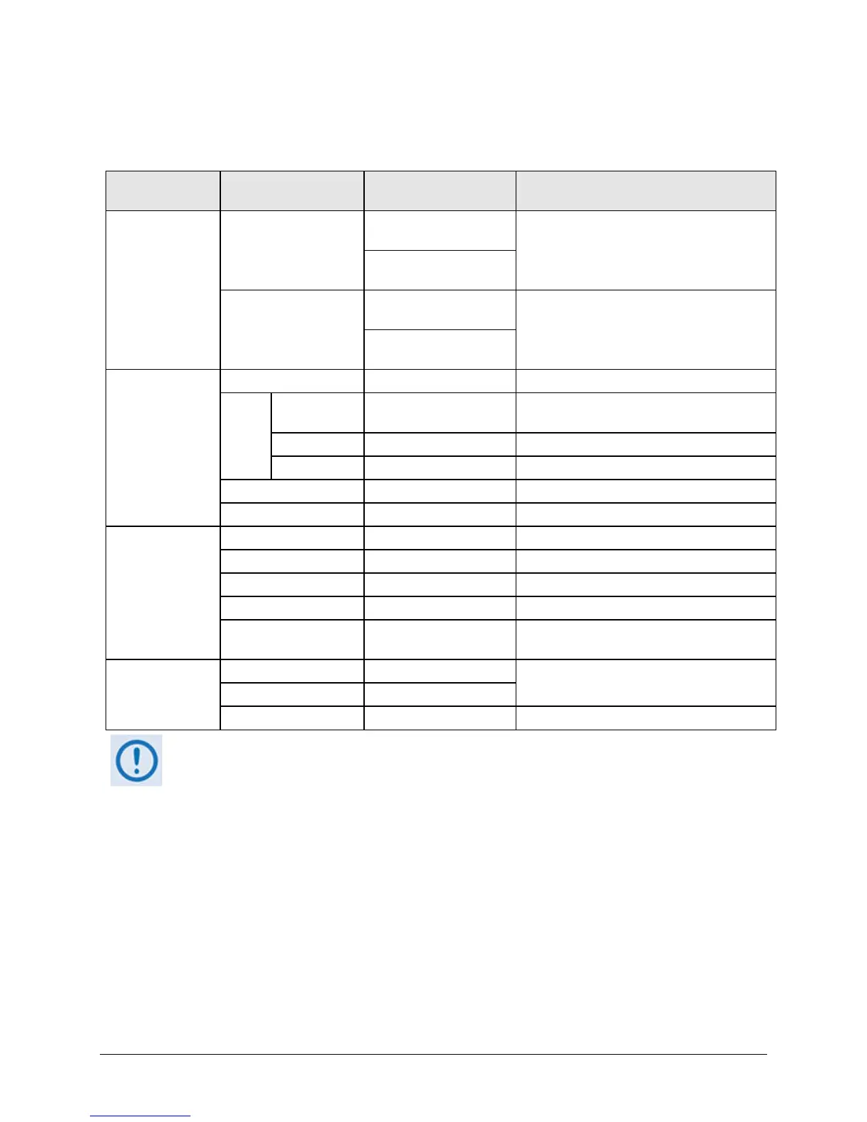
Table 3-1. Rear Panel External Connections
Connector Group
(Sect. Ref.)
Name Connector Type Function
IF
(Sect. 3.2)
Rx
CDM-570L: Type ’N’
female (L-Band)
IF Input
CDM-570: BNC female
(70/140MHz band)
Tx
CDM-570L: Type ’N’
female (L-Band)
IF Output
CDM-570: BNC female
(70/140MHz band)
Terrestrial Data
(Sect. 3.3)
Data Interface 25-pin Type ‘D’ female Serial synchronous data Input/Output
G.703
Data
Balanced 15-pin Type ‘D’ female
G.703
T1 (1544 kbps) / E1 (2048 kbps)
Unbalanced Out
BNC 75Ω female Receive G.703 E1 (2048 kbps)
Unbalanced In BNC 75Ω female Transmit G.703 E1 (2048 kbps)
10/100 Ethernet M&C RJ-45 female 10/100 BaseT management and data
10/100 Ethernet Traffic RJ-45 female (w/optional IP Module) Ethernet Traffic
Utility
(Sect. 3.4)
Remote Control 9-pin Type ‘D’ male Serial Remote Interface (EIA-232/-485)
Alarms 15-pin Type ‘D’ male Form C Alarms (relay closures)
1:1 Control 9-pin Type ‘D’ female Connection to External 1:1 Controller
External Reference BNC female Input/Output
Serial Console RJ-11 female
(w/optional IP Module) EIA-232 Serial Console
for CDM-570L/IP Module management
Power/Ground
(Sect 3.5)
AC See Sect. 3.5.1
Chassis power
DC (Optional) See Sect. 3.5.2
Ground #10-32 stud Common Chassis Ground
The European EMC Directive (EN55022, EN50082-1) requires using properly shielded
cables for DATA I/O. These cables must be double-shielded from end-to-end, ensuring a
continuous ground shield.