CDM-570/570L Satellite Modem with Optional IP Module Revision 12
Rear Panel Connectors and Pinouts MN/CDM570L.IOM
3–9
Table 3-6. Alarm Interface Connector Pin Assignments
Pin # Signal Function Name
8
15
7
Rx Traffic (De-energized, Faulted)
Rx Traffic (Energized, No Fault)
Rx Traffic
RX-NC
RX-NO
RX-COM
14
6
13
Tx Traffic (De-energized, Faulted)
Tx Traffic (Energized, No Fault)
Tx Traffic
TX-NC
TX-NO
TX-COM
5
12
4
Unit Fault (De-energized, Faulted)
Unit Fault (Energized, No Fault)
Unit Fault
UNIT-NC
UNIT-NO
UNIT-COM
11
3
Rx I Channel (Constellation monitor)
Rx Q Channel (Constellation monitor)
RX-I
RX-Q
10 No Connection N/C
2 AGC Voltage (Rx signal level, 0 to 10 volts) AGC
9 EXT Carrier OFF EXT-OFF
1 Ground GND
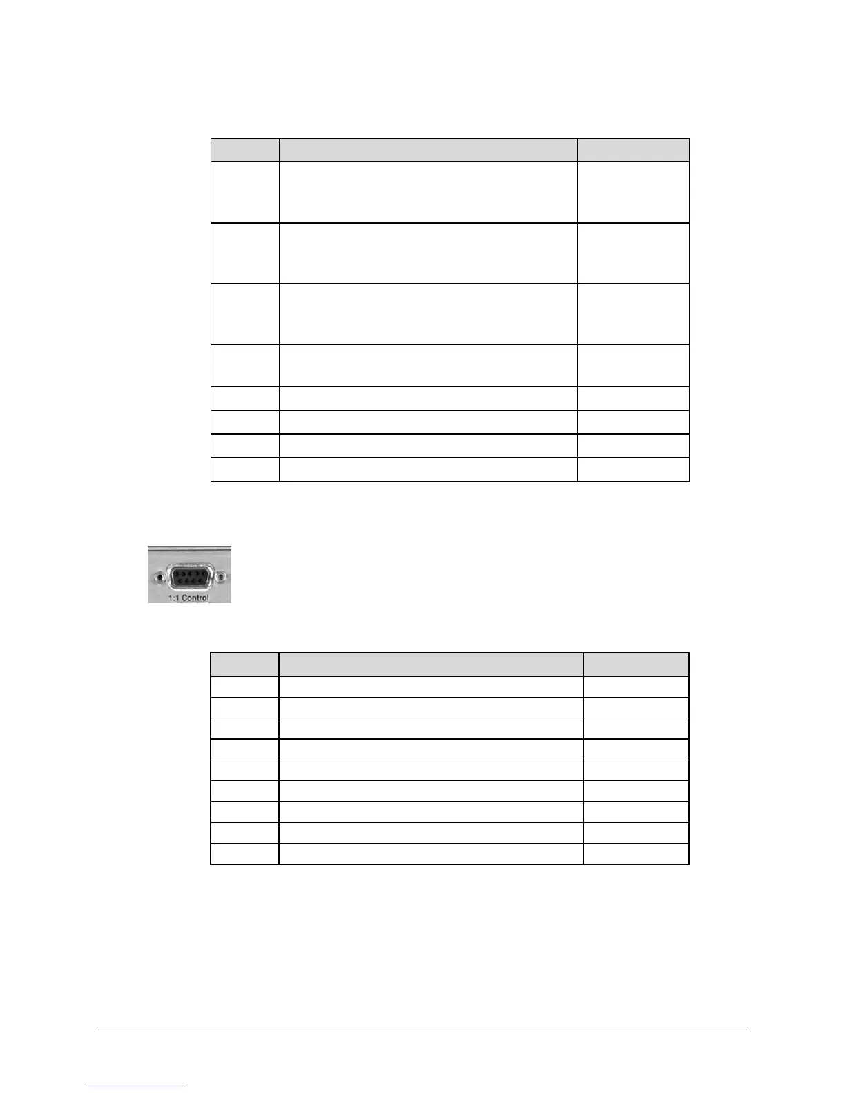
3.4.3 1:1 Control Interface Connector, DB-9F
The 1:1 Control connection is a 9-pin type ‘D’ female connector (DB-9F). This
connector is used to connect the modem only to a CRS-170 switch in 1:1
redundancy configurations.
Table 3-7. 1:1 Control Interface Connector Pin Assignments
Pin # Description Direction
1 Ground
2 Receive Serial Data – auxiliary channel In
3 Redundancy In 1 In
4 Redundancy In 2 In
5 Ground
6 Transmit Serial Data – auxiliary channel Out
7 Redundancy Out 1 Out
8 Redundancy Out 2 Out
9 Fused +12 volt Out