CDM-570/570L Satellite Modem with Optional IP Module Revision 12
Rear Panel Connectors and Pinouts MN/CDM570L.IOM
3–8
3.4 Utility Connections
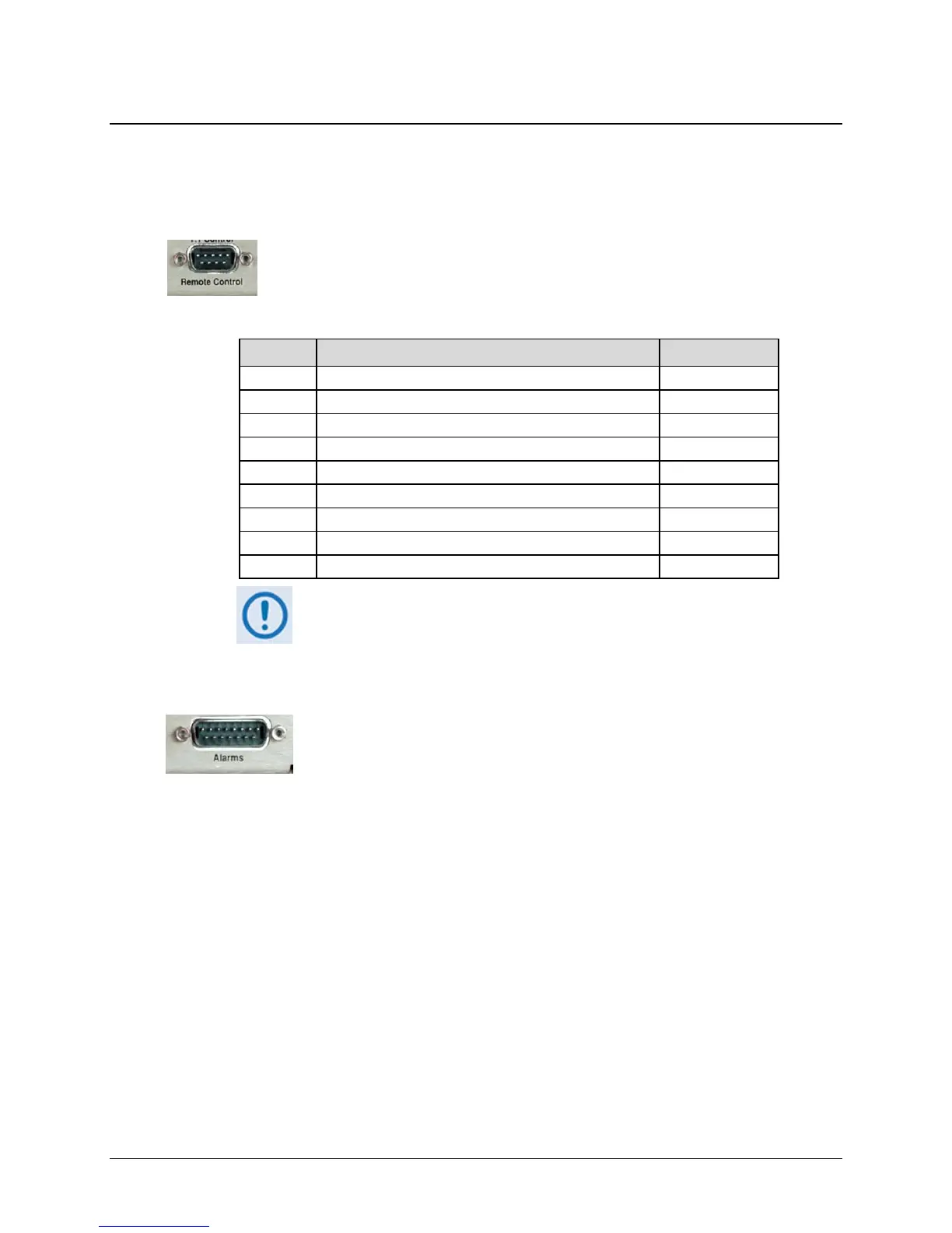
3.4.1 Remote Control Interface Connector, DB-9M
The Remote Control interface connection is a 9-pin type ‘D’ male (DB-9M)
connector. This port is intended for connection to an M&C computer, or terminal
device. This interface is user-selectable for either EIA-232 or EIA-485.
Table 3-5. Remote Control Interface Connector Pin Assignments
Pin # Description Direction
1 Ground
2 EIA-232 Transmit Data Out
3 EIA-232 Receive Data In
4 Reserved - do not connect to this pin
5 Ground
6 EIA-485 Receive Data B * In
7 EIA-485 Receive Data A * In
8 EIA-485 Transmit Data B Out
9 EIA-485 Transmit Data A Out
* Use for 2-wire EIA-485 operation
3.4.2 Form-C Traffic Alarms Connector, DB-15M
The Alarms connector is a 15-pin type 'D' male (DB-15M) connector. Unit
alarms are provided on this connector, affording user access to the Form-C
relay contacts which indicate the fault status of the unit. These contacts are
typically connected to an external fault monitoring system often found in
satellite earth stations. Additionally, the receive I and Q demodulator samples are provided on
this connector. Connecting these signals to an oscilloscope in X,Y mode will provide the receive
signal constellation diagram, which is a useful diagnostic aid. A pin is also provided which can
mute the transmit carrier; this requires that the pin be shorted to ground or a TTL ‘low’, or that an
EIA-232 ‘high’ signal be applied.
As an aid to antenna pointing or for driving step-track equipment, an analog AGC signal is
provided on Pin 2 of this connector.
See
32Table 3-6 on the next page for the Alarms connector pinouts.