ESAB Cutting Systems
CROSSBOW Page 155
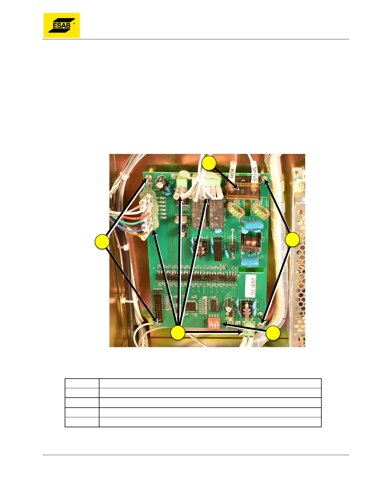
5.6.9 Replacing VHC Sensor Board
If the VHC Sensor Board requires replacement, use the following procedure:
1) Follow above procedure for Servicing Operator Panel Components.
2) Carefully note the position of wires connected to terminal strip on top of board.
3) Note the position of the DIP Switches 1 through 4.
4) Un-wire two wires from terminal strip.
5) Un-plug wire connectors from board.
6) Remove four mounting screws at corners of board.
7) Board may now be removed and replaced.
Figure 121: Initial Height Sensing Board
Number Description
1 Wire Terminals
2 Mounting Screws
3 Connector Plug
4 DIP Switches