ESAB Cutting Systems
CROSSBOW Page 157
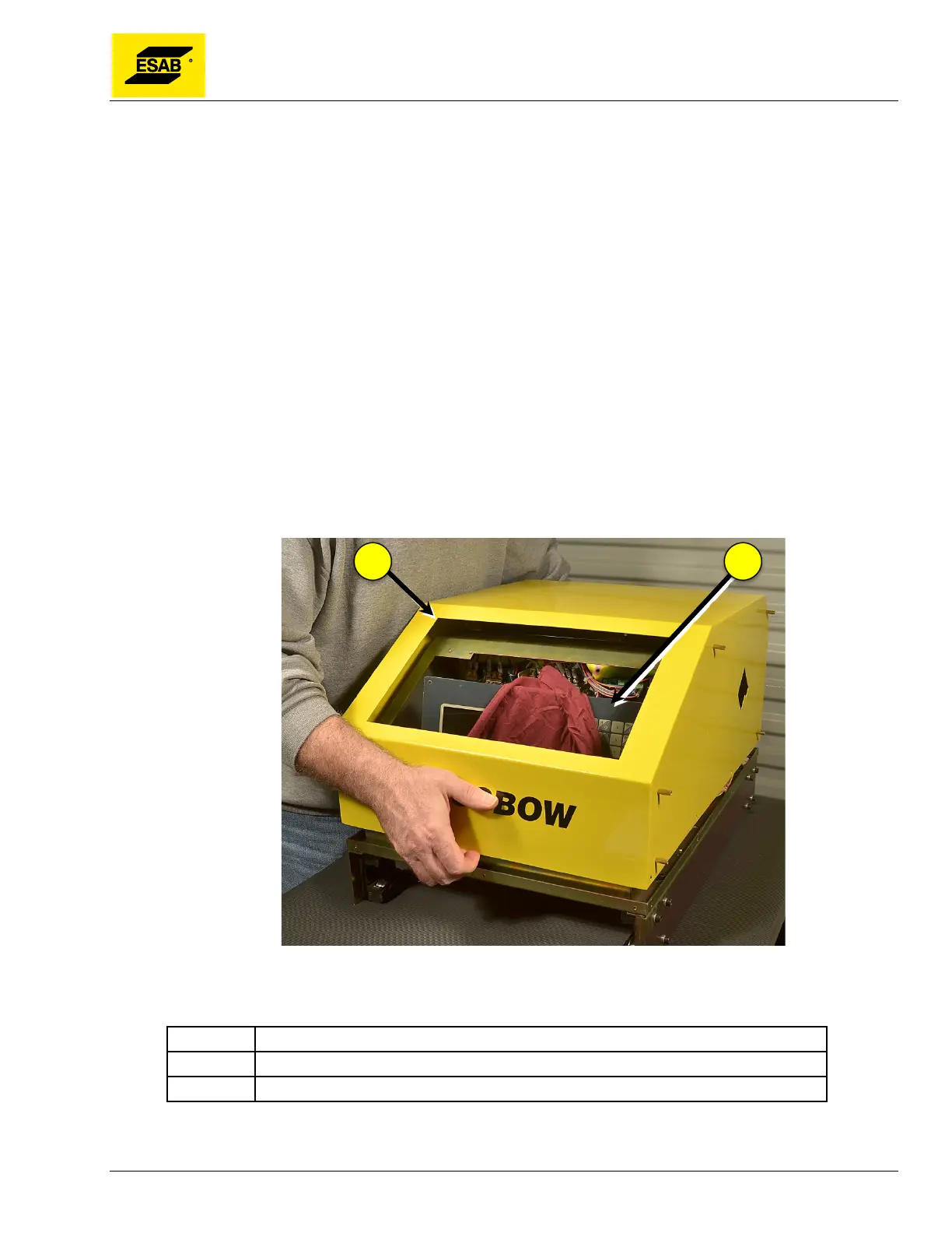
5.6.11 Removing the Cover
If the Central Unit cover must be removed, follow this procedure:
1) Disconnect all incoming power.
2) Disconnect all cables from Connector Panel on rear of Central Unit.
3) Disconnect hoses and cables from end of Cross Beam.
4) Open Cable Holder on left end of Cross Beam and remove torch lead.
5) Remove Cable Holder from left end of Cross Beam by loosening clamp and sliding off end of
beam.
6) Carefully remove Cross Beam from Central Unit and set in a safe place, being careful to avoid
damaging drive rack, inlet connections, and process tools on end of Cross Beam.
7) Remove all screws mounting Heat Shield to side of Central Unit. Do not remove Stand-Offs.
8) Remove all screws mounting CNC and Control Switch Panel to front of Central Unit.
9) Remove all screws holding cover on Central Unit.
10) Carefully lift CNC out of front panel. While holding CNC unit, lift Control Switch Panel and
gently set it inside the electrical cabinet. Place a clean towel or other material inside the
electrical cabinet as padding for the CNC. Carefully set the CNC inside the electrical cabinet.
11) Carefully lift cover off main unit and set it aside.
Figure 123: Removing the Cover
Number Description
1 Central Unit Cover
2 CNC Unit
Now all internal components can be accessed and serviced.