ESAB Cutting Systems
CROSSBOW Page 162
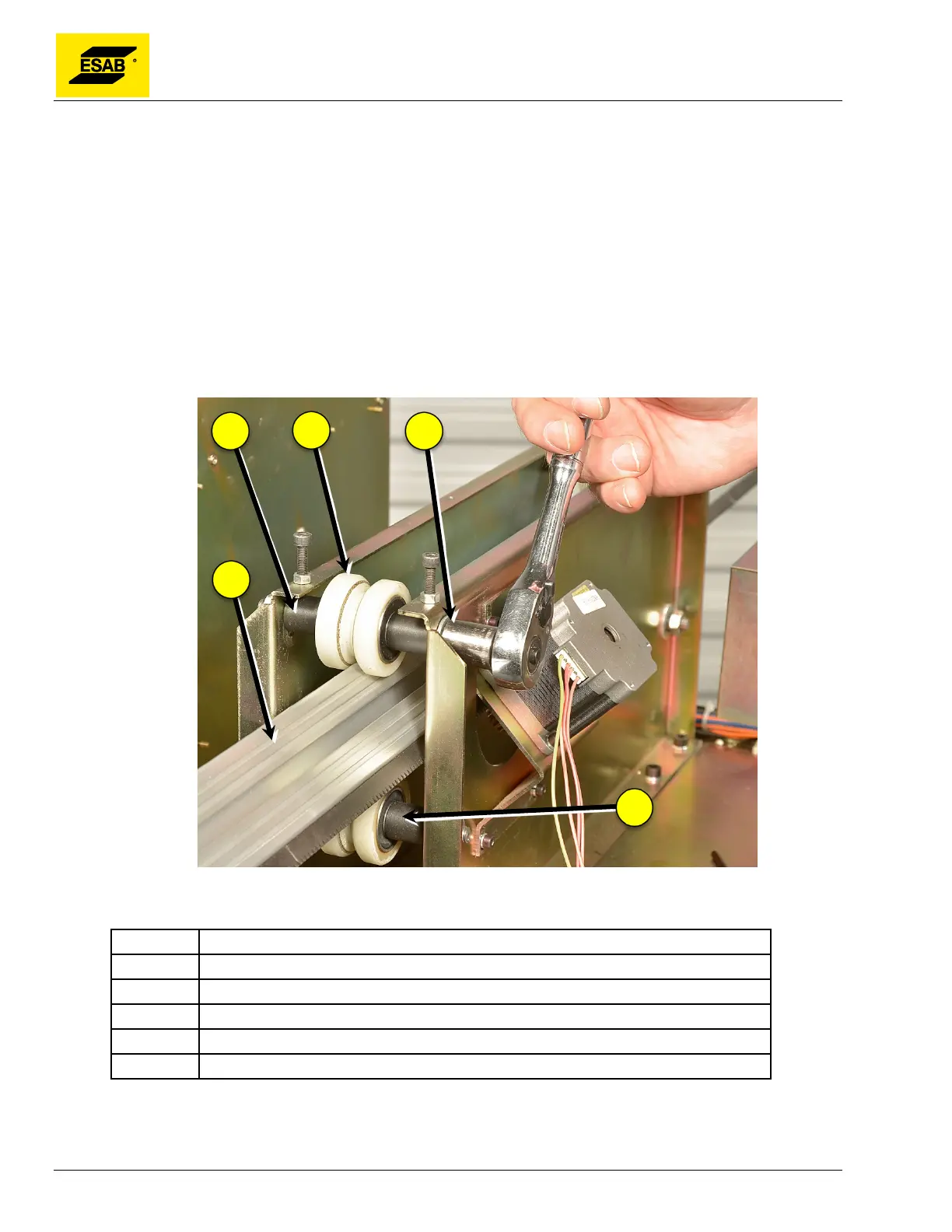
5.6.16 Adjusting the V-Wheels
If the Cross Beam becomes loose between the V-Wheels inside the Central Unit, the V-Wheel tension
needs to be adjusted. Use the following procedure:
1) Follow above procedure for Removing the Cover.
2) Re-Insert Cross Beam through Central Unit while cover is removed. Do not reassemble Cable
Holders or other items to Cross Beam.
3) Loosen four screws holding Motor Mounting Plate to Rear Cross Drive Mount Panel, and slide
Cross Beam Drive Motor down to disengage the pinion.
4) Loosen all four Shaft Mounting Nuts on both ends of both upper V-Wheel Shafts. Do not
loosen lower shafts. Upper shafts are adjustable, lower shafts are fixed.
Figure 128: Loosening V-Wheel Shaft
Number Description
1 Upper V-Wheel Shaft (Adjustable)
2 V-Wheels
3 V-Wheel Shaft Mounting Nut
4 Cross Beam
5 Lower V-Wheel Shaft (Fixed)
5) Loosen Lock Nut on each Tension Screw.
6) Adjust V-Wheel tension by tightening the tensioner screws on top of the Cross Drive Mounting