ESAB Cutting Systems
CROSSBOW Page 163
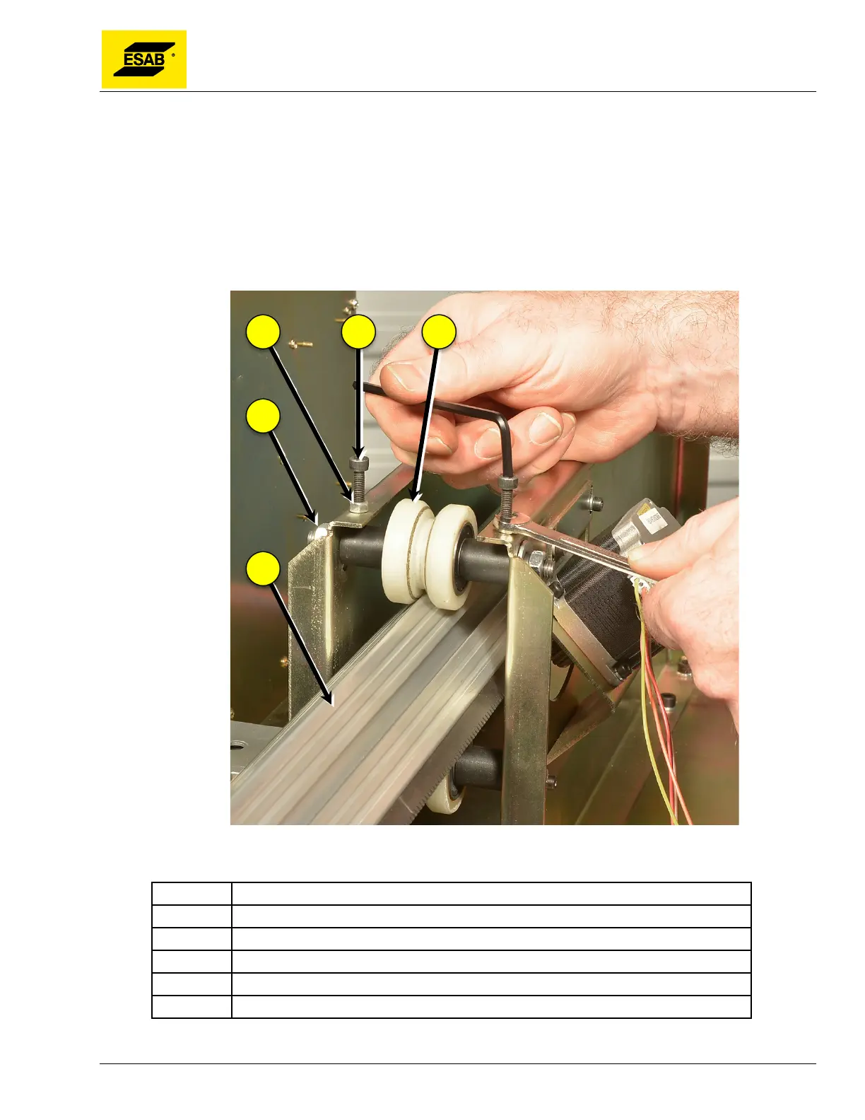
Panels. Adjust until the Cross Beam moves freely in the Y-Axis, but without any motion
vertically between the V-Wheels.
7) Tighten Shaft Mounting Nuts, then re-check tightness and motion of Cross Beam.
8) Tighten Lock Nuts while holding Tension Screw with a wrench.
9) Re-check tightness of V-Wheels and motion of Cross Beam. Do no over-tighten it will bind the
motion.
10) Follow the above procedure for Adjusting Drive Pinion Engagement.
Figure 129: V-Wheel Tension Screw Adjustment
Number Description
1 Lock Nut
2 Tension Screw
3 V-Wheels
4 Shaft Mounting Nut
5 Cross Beam